Rigid & Special Couplings
MAL Friction Safety Coupling
MAL Friction Safety Coupling with model-specific technical data, engineering context and assembly drawing for preliminary selection.
Product Overview
MAL is a friction safety coupling with separate minimum and maximum slip-torque fields, driving and driven bore dimensions, chain number, D/MD/S geometry, mass and inertia. This architecture is selected by the desired overload response and the two shaft interfaces, then checked for speed, reset access and guarding. The published model tables contain 17 size rows and provide torque values spanning 6.3–4500 N·m, permissible-speed values spanning 140–1000 r/min, bore values spanning 10–130 mm. Use those values for preliminary comparison only; final materials, current standards, manufacturing details and operating suitability require confirmation from RONGXING DRIVE.
Key Features
- Friction-based overload protection
- Independent minimum and maximum slip-torque values
- Driving/driven bores and chain number by model
- The model data provides torque values spanning 6.3–4500 N·m, permissible-speed values spanning 140–1000 r/min, bore values spanning 10–130 mm for a traceable preliminary comparison.
Typical Selection Context
- Conveyors, mixers and process equipment needing slip protection
- Drive lines where a defined torque limit protects downstream machinery
Technical Specification
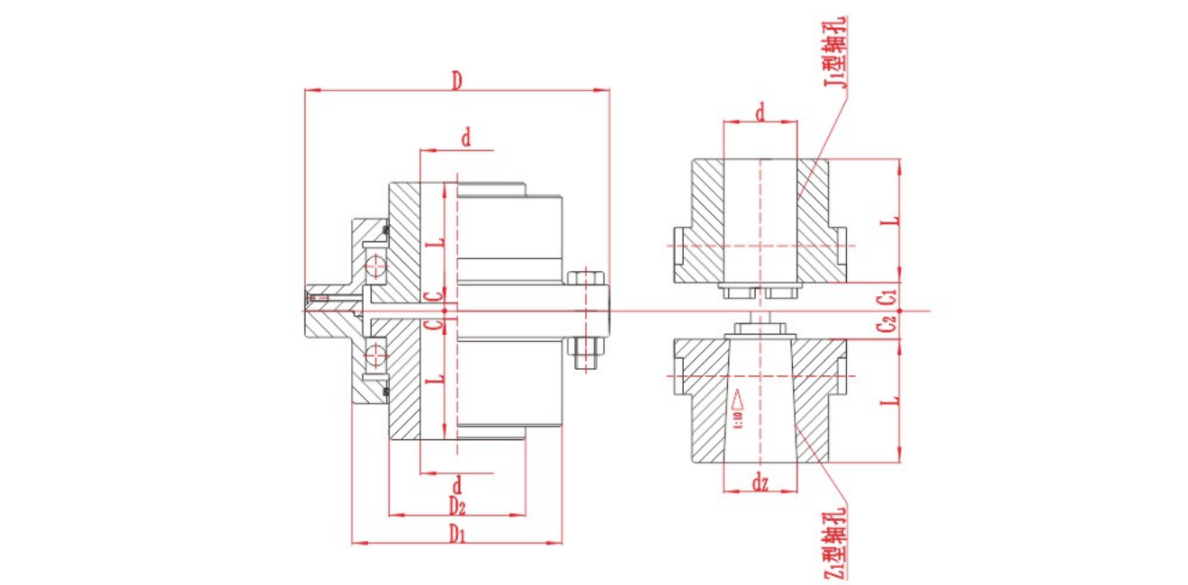
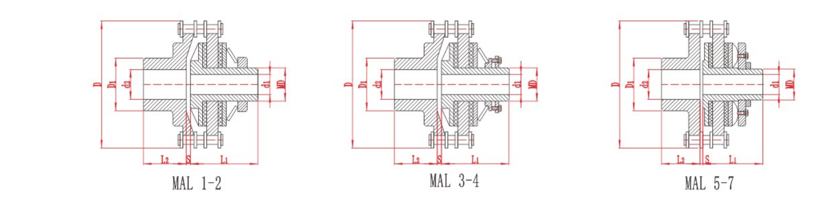
The following model tables are provided for preliminary comparison. Keep the relevant assembly drawing with the selected row.
| Model | Slip torque Tn N·m min | Slip torque Tn N·m max | Permissible speed r/min | Bore dimensions Driving end d₁ | Bore dimensions Y L₁ | Bore dimensions Driven end d₂ | Bore dimensions J₁ L₂ | Chain number | D | MD | D₁ | S | Mass kg | Mass moment of inertia kg·m² |
|---|---|---|---|---|---|---|---|---|---|---|---|---|---|---|
| MAL1Q | 6.3 | 28 | 1000 | 10~19 | 52 | 14~28 | 27~44 | TG127×2 | 101 | M33×1.5 | 60 | 3.7 | 3.0 | 0.003 |
| MAL1Z | 14 | 56 | 1000 | 16~24 | 52 | 18~38 | 30~60 | |||||||
| MAL2Q | 20 | 80 | 800 | 16~25 | 62 | 18~38 | 30~60 | TG158×2 | 137 | M42×1.5 | 80 | 4.2 | 8.0 | 0.014 |
| MAL2Z | 40 | 140 | 800 | 19~30 | 62 | 20~45 | 38~84 | |||||||
| MAL3Q | 63 | 224 | 500 | 20~35 | 75~82 | 20~48 | 38~84 | TG190×2 | 188 | M65×2 | 110 | 3.7 | 18.9 | 0.061 |
| MAL3Z | 90 | 400 | 500 | 25~45 | 75~112 | 30~65 | 60~107 | |||||||
| MAL4Q | 125 | 560 | 400 | 30~50 | 100~112 | 30~70 | 60~107 | TG254×2 | 250 | M90×2 | 150 | 5.2 | 46.5 | 0.658 |
| MAL4Z | 224 | 1120 | 400 | 35~63 | 100~142 | 40~90 | 84~132 | |||||||
| MAL5Q | 400 | 1400 | 300 | 38~65 | 120~142 | 40~75 | 84~107 | TG444×2 | 354 | M100×2 | 130 | 5.8 | 76.5 | 0.921 |
| MAL5Z | 630 | 2000 | 300 | 42~71 | 120~142 | 45~85 | 84~132 | |||||||
| MAL6Q | 900 | 2800 | 200 | 40~75 | 150 | 45~85 | 84~132 | TG508×2 | 470 | M150×2 | 145 | 5.4 | 155 | 3.726 |
| MAL6Z | 2000 | 4000 | 200 | 65~100 | 150~212 | 65~100 | 132~167 | |||||||
| MAL7Q | 2500 | 5000 | 140 | 70~110 | 190~212 | 80~140 | 132~202 | TG508×2 | 631 | M190×2 | 250 | 10 | 335 | 8.249 |
| MAL7Z | 4500 | 10000 | 140 | 95~130 | 190~252 | 110~170 | 167~242 |
| Size | MAL1 Q/Z | MAL2 Q/Z | MAL3 Q/Z | MAL4 Q/Z | MAL5 Q/Z | MAL6 Q/Z | MAL7 Q/Z |
|---|---|---|---|---|---|---|---|
| Axial | ±0.95 | ±1.15 | ±1.4 | ±1.9 | ±3.3 | ±3.8 | ±3.8 |
| Radial | 0.25 | 0.32 | 0.38 | 0.50 | 0.88 | 1.0 | 1.0 |
| Angular | 1° |
Engineering Context
This model is best understood from its own construction: Friction-based overload protection; Independent minimum and maximum slip-torque values; Driving/driven bores and chain number by model Industry selection practice checks torque and speed together with the movement, shaft interface, installation envelope and maintenance conditions allowed by that construction.
Technical Notes
- Model symbols, units and empty or placeholder cells are shown as published.
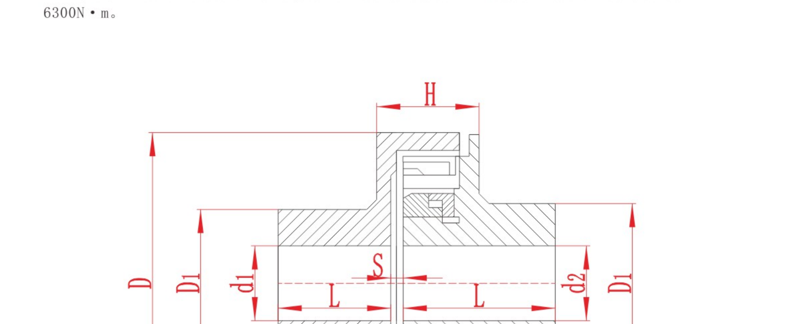
- Dimension letters must be interpreted with the relevant assembly drawing.
- Published values support preliminary review and do not replace final engineering confirmation.
Assembly Drawing
Information Required for Selection
- Set the required slip window from normal, starting and peak torque
- Confirm bores, chain, speed, reset access, guard and inertia
- Send the exact model row, assembly drawing and actual duty data with the inquiry.
Product FAQ
How is MAL different from a normal coupling?
MAL is selected around an overload-release setting as well as torque transmission and shaft fit.
Why are minimum and maximum slip values both needed?
They define the acceptable setting window for the protection function.
Are the published values final ordering values?
No. They are preliminary engineering data; confirm the selected model, drawing, dimensions, materials, standard and suitability with RONGXING DRIVE.
Technical data is provided for preliminary selection. Confirm the final model, dimensions, materials, applicable standard and operating suitability with RONGXING DRIVE before quotation, manufacture or installation.