
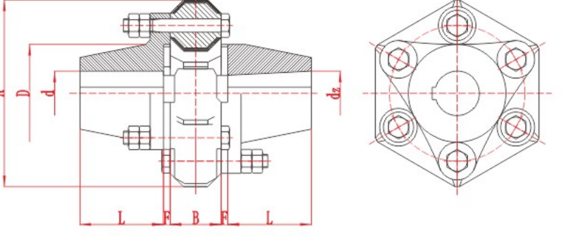
DL Multi-Jaw Coupling
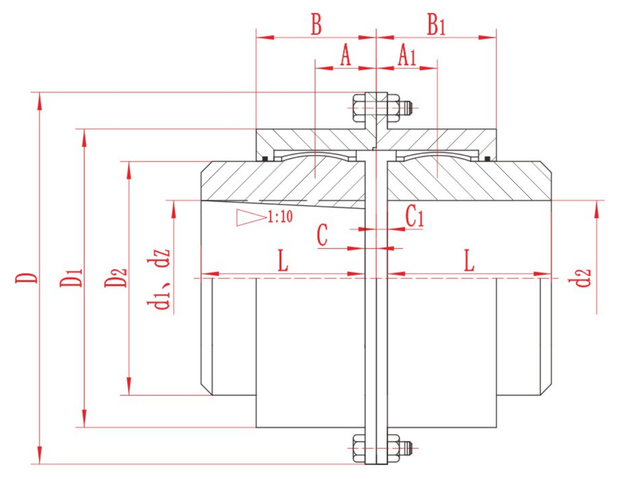
DL Multi-Jaw Coupling with technical data and assembly drawing for preliminary selection.
View DL Multi-Jaw Coupling DetailsCurated technical topic
A coupling should be selected from the connected machine, not from a keyword or shaft diameter in isolation. Use the workflow below to narrow the family first and then confirm a model against its own technical table and drawing.
The four product families cover different structural solutions. A concise operating-data package lets RONGXING DRIVE check the family, size, materials and any special interface details before quotation.
The machine duty, speed, nominal and peak torque, both shaft interfaces, expected displacement and the installation environment are the most useful starting facts.
DL Multi-Jaw Coupling with technical data and assembly drawing for preliminary selection.
View DL Multi-Jaw Coupling Details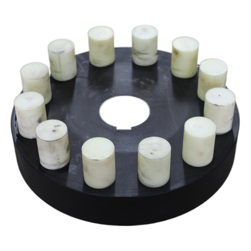
HL Flexible Pin Coupling with technical data and assembly drawing for preliminary selection.
View HL Flexible Pin Coupling Details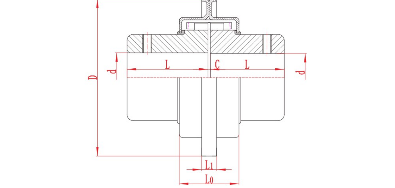
JSB Grid Coupling with technical data and assembly drawing for preliminary selection.
View JSB Grid Coupling Details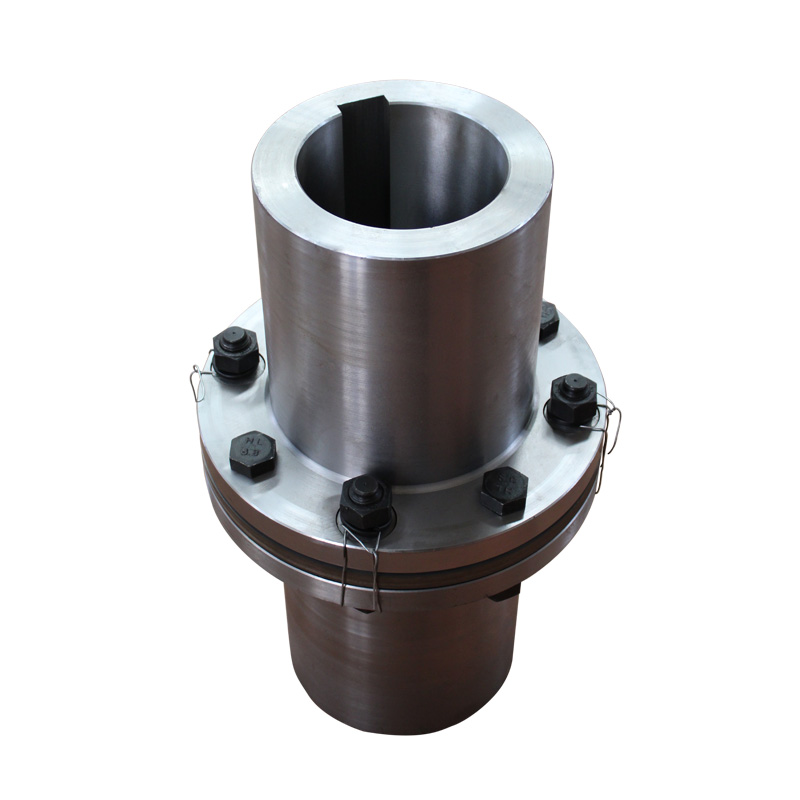
JZM Diaphragm Coupling for Heavy Machinery with technical data and assembly drawing for preliminary selection.
View JZM Diaphragm Coupling for Heavy Machinery Details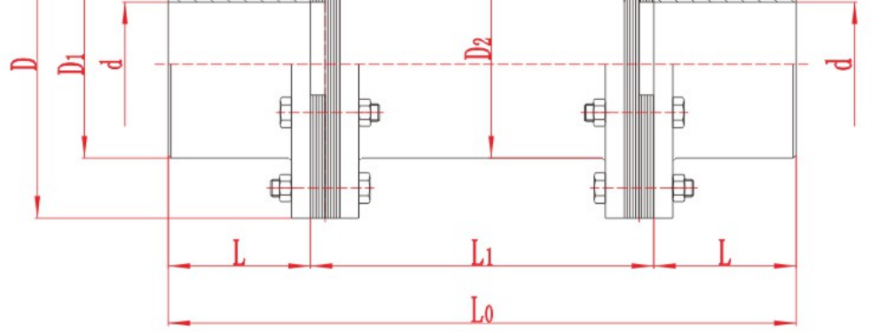
JZMJ Diaphragm Coupling for Heavy Machinery with technical data and assembly drawing for preliminary selection.
View JZMJ Diaphragm Coupling for Heavy Machinery Details
LA Tire Coupling with technical data and assembly drawing for preliminary selection.
View LA Tire Coupling Details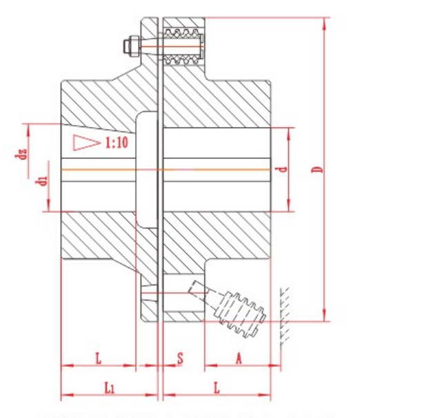
Compare TL and TLL pin bush coupling dimensions and drawings, with 22 model rows and an English PDF catalogue for preliminary selection.
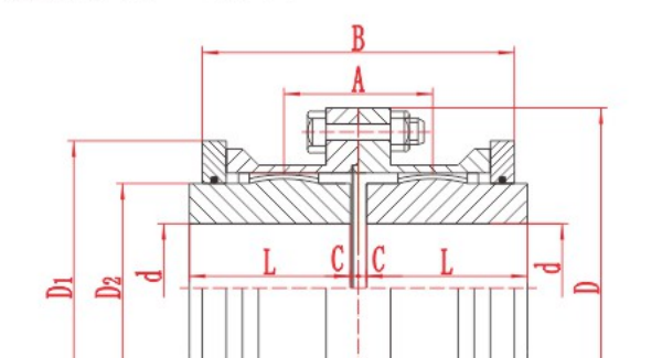
A full gear coupling has two flexible gear meshes, one at each end. A half gear coupling, often called a flex-rigid coupling, has one flexible gear mesh and one rigid connection. When a purchase order says “half gear coupling”, check the drawing and the scope of supply. The term can also refer to a single flexible half sold as a component.
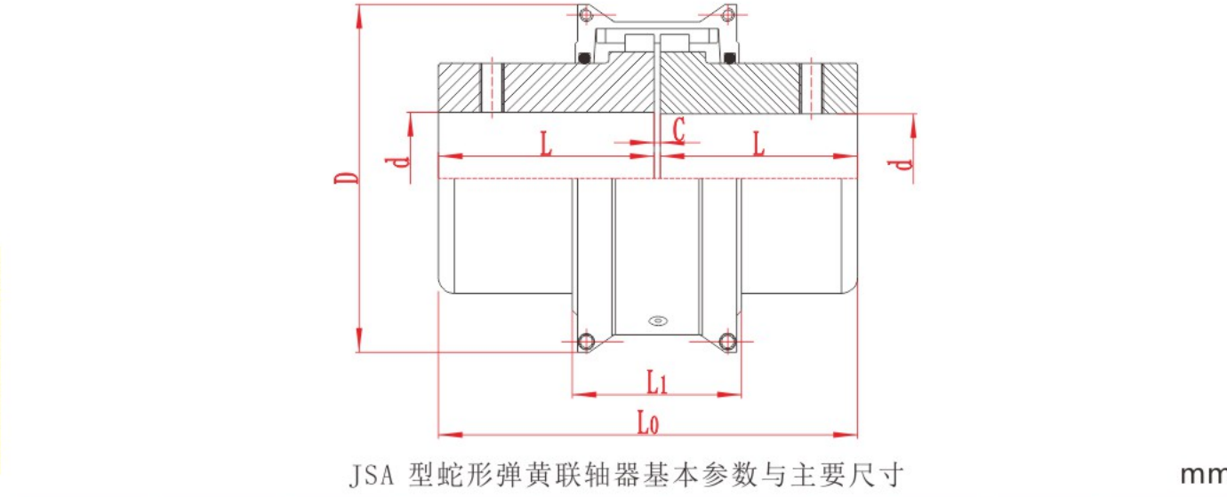
Use the same torque history, installation dimensions and maintenance constraints to compare gear and grid couplings for a shock-loaded drive.

Identify angular, parallel and axial misalignment. Learn how to measure each one and check the installation tolerance for a flexible coupling.
Before operating a gear coupling, confirm the approved lubricant, the fill quantity and units, the filling method and the next service interval for the exact model. Inspect the seals and plugs, then confirm whether the coupling was filled during asse
To confirm a gear coupling installation gap, identify the series, size and assembly arrangement. Use the approved drawing or installation manual to find the specified distance, the two faces it is measured between and its tolerance. Record the actual
Topic FAQ
No. Include the speed at the coupling, driven-machine duty, peak loads, shaft interfaces, misalignment and environment. Bore fit is only one check; it does not confirm torque capacity, speed suitability or the required maintenance clearance. Check the data needed for coupling selection before shortlisting a model from bore size alone.
Separate the requirements for torque transmission, displacement, torsional behaviour and maintenance. Compare suitable structures against those requirements, then check the model-specific torque, speed, bore and space limits. Keep application assumptions visible during the comparison.
Include the technical duty sheet, both shaft interfaces, required drawing or model, quantity and inspection requirements. Add the delivery destination and requested commercial terms. Price and delivery should be confirmed in a written quotation for that specification.
Send torque, speed, shaft and installation data for a preliminary review.