
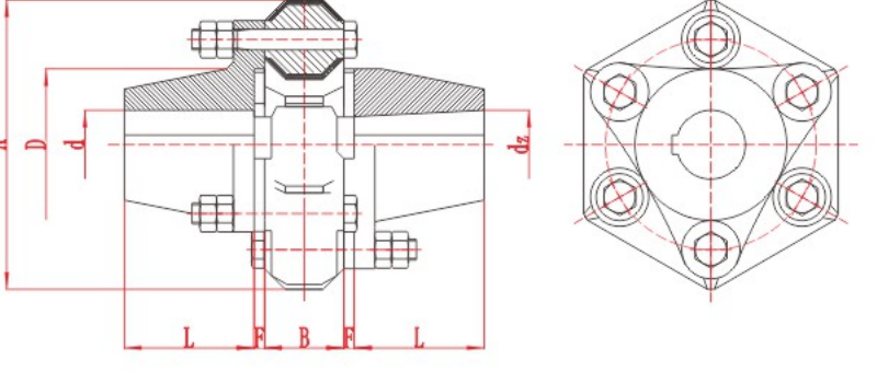
DL Multi-Jaw Coupling
DL Multi-Jaw Coupling with technical data and assembly drawing for preliminary selection.
View DL Multi-Jaw Coupling DetailsCurated technical topic
A motor coupling connects an electric motor shaft to the shaft of a pump, fan, gearbox or other driven machine to transmit torque. Common industrial options include jaw, pin bush, tire, grid, gear and diaphragm couplings. A motor shaft coupling must match both shaft interfaces and the operating duty. When selecting a motor flex coupling, compare the flexible element, permissible shaft movement, torsional behaviour and maintenance requirements, then check the model table and assembly drawing.
Start with the motor and the machine it drives. Record the operating speed, power or torque, starting and peak loads, and frequency of starts or reversals. Measure both shaft diameters, usable shaft lengths and keyways, together with the distance between shaft ends (DBSE) and the available installation space. Use these details to compare coupling structures before selecting a size.
| Structure | Models to compare | Checks before selection |
|---|---|---|
| Jaw | ML, XL, XLS, DL | Elastomer arrangement, both bores, torque, speed and clearances. |
| Pin bush | TL, HL | Pin and resilient element arrangement, shaft engagement and inspection access. |
| Tire | LA, LB, UL | Tire element, shaft movement, temperature and replacement access. |
| Grid | JSA, JSB | Grid arrangement, lubrication, load changes and cover clearance. |
| Gear | GICL, GIICL and related series | Tooth arrangement, torque, speed, bores, shaft movement and lubrication. |
| Diaphragm | JZM, JZMJ | Metallic flexible element, torsional stiffness, shaft spacing and model-specific limits. |
Send the motor and driven-machine details, power in kW or torque in N·m, speed in r/min, starting and peak loads, and the frequency of starts, reversals or braking. Include both shaft diameters, usable shaft lengths, keyways and fits, DBSE in mm, alignment conditions, temperature and maintenance space. For a replacement, attach the existing assembly drawing or model information.
DL Multi-Jaw Coupling with technical data and assembly drawing for preliminary selection.
View DL Multi-Jaw Coupling Details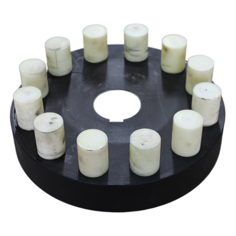
HL Flexible Pin Coupling with technical data and assembly drawing for preliminary selection.
View HL Flexible Pin Coupling Details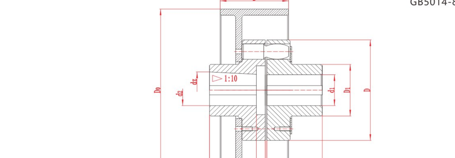
HLL Flexible Pin Coupling with Brake Drum with technical data and assembly drawing for preliminary selection.
View HLL Flexible Pin Coupling with Brake Drum Details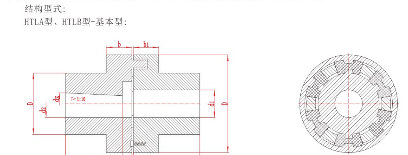
HTLA H-Type Flexible Coupling with technical data and assembly drawing for preliminary selection.
View HTLA H-Type Flexible Coupling Details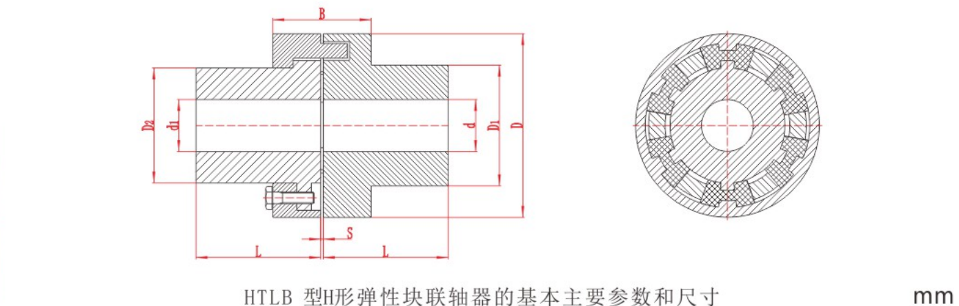
HTLB H-Type Flexible Block Coupling with technical data and assembly drawing for preliminary selection.
View HTLB H-Type Flexible Block Coupling Details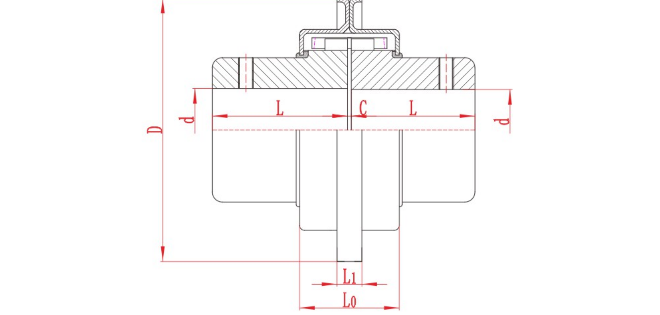
JSB Grid Coupling with technical data and assembly drawing for preliminary selection.
View JSB Grid Coupling Details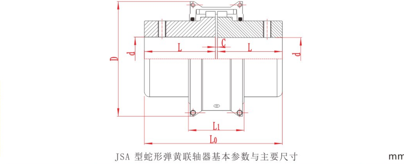
Use the same torque history, installation dimensions and maintenance constraints to compare gear and grid couplings for a shock-loaded drive.

Identify angular, parallel and axial misalignment. Learn how to measure each one and check the installation tolerance for a flexible coupling.

Start pin bush coupling selection with the load and speed at the coupling, then check both shaft ends and the space around the assembly. A pin bush coupling transmits torque through pins and resilient bushes between its flanges. The pins, bushes and
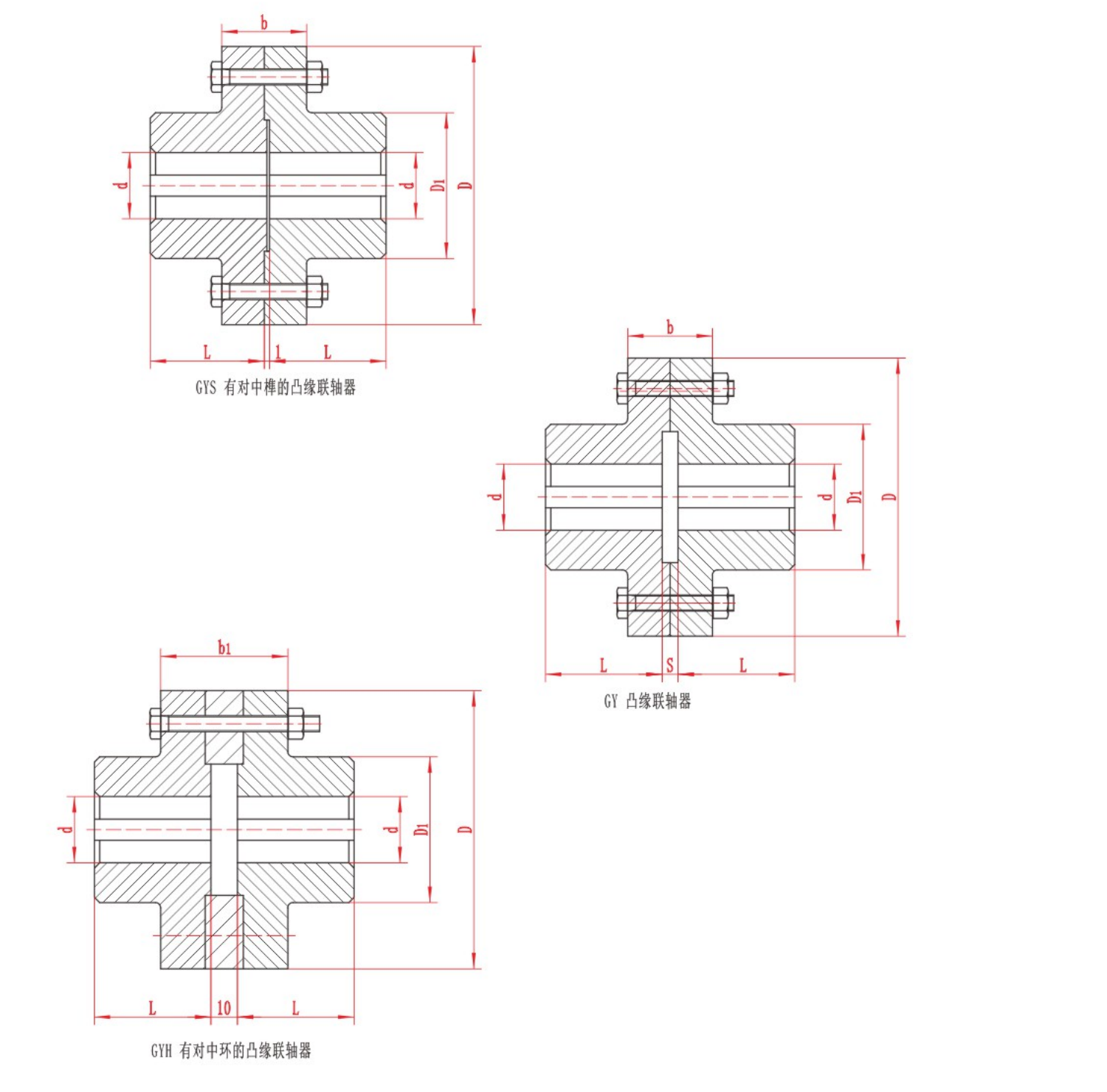
The two main types of mechanical shaft coupling are rigid and flexible. A rigid coupling joins shafts without a flexible element and depends on the required alignment being maintained. A flexible coupling accommodates limited movement within the limi
For an industrial pump replacement, start with the pump maker’s coupling specification and the installed drawing. Compare a pin bush coupling when the pump already has a flanged pin-and-bush arrangement you want to retain. A jaw coupling is a candida

Jaw couplings transmit torque through an elastomer between two metal hubs. Common descriptions include straight-jaw and curved-jaw profiles, solid and wrap-style spiders, and close-coupled or spacer assemblies. Each describes a different part of the
Topic FAQ
A motor coupling connects a motor shaft to a driven shaft and transmits torque between them. The coupling structure determines its stiffness, permissible shaft movement and maintenance requirements.
In shaft transmission applications, both terms describe the connection between a motor shaft and a driven shaft. The model and assembly drawing identify the actual structure, shaft interfaces and installation dimensions.
Motor flex coupling is a common search term for a flexible coupling used on a motor drive. Flexible designs can use elastomeric elements, grids, gear meshes or metallic diaphragms. Their permitted movement and torsional behaviour depend on the design.
Provide operating power or torque, speed, starting and peak loads, both shaft interfaces and the installed shaft spacing. Compare suitable structures, then verify the selected size against its torque, speed, bore, displacement and installation limits.
Yes, when the coupling design supports the required bore combination. Check each hub separately for bore diameter, shaft engagement, keyway and fit, then confirm that the complete coupling meets the operating duty.
Some flexible designs provide torsional compliance and damping. Metallic diaphragm couplings can be torsionally stiff while allowing specified shaft movement. Assess damping, stiffness and misalignment capacity separately for the selected structure and duty.
Power and speed help establish running torque. Starting loads, peak torque, duty cycle, both shaft interfaces, permitted movement and installation space also affect the selection.
Consider a spacer arrangement when the shafts are separated or when servicing requires clearance between the machines. Check the installed DBSE, whether the centre section can be removed, and the withdrawal space needed for the equipment being serviced.
Send torque, speed, shaft and installation data for a preliminary review.