
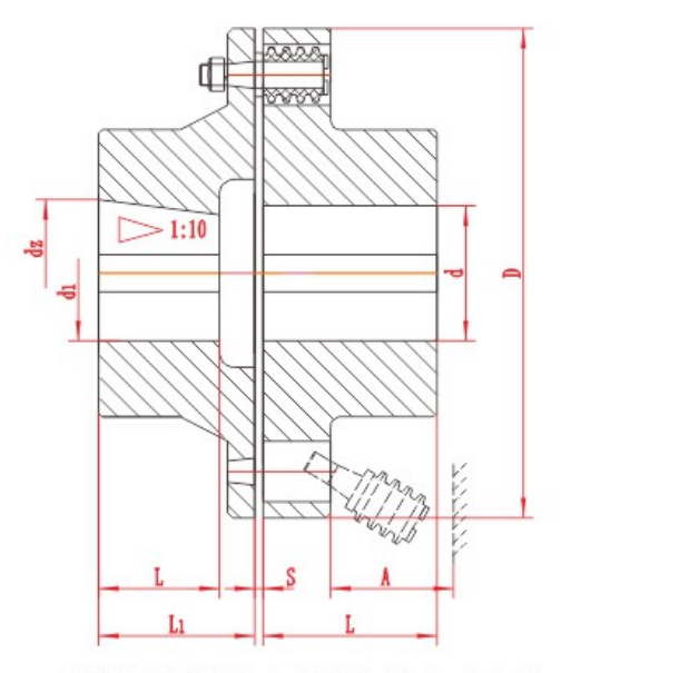
Pin Bush Coupling Size Chart, Dimensions and Drawings
Compare TL and TLL pin bush coupling dimensions and drawings, with 22 model rows and an English PDF catalogue for preliminary selection.
Resource library
Engineering-oriented guidance for preliminary coupling and cardan-shaft selection, specification comparison, inquiry preparation and clear technical communication.
This library supports preliminary coupling and cardan-shaft decisions. Start with the machine duty, use the selection guidance to identify the information that is missing, and then open the relevant model page for its own table and drawing. Published values are for engineering comparison; final suitability remains subject to confirmation against the complete operating conditions.
Record the driving and driven equipment, power, operating speed, nominal torque, peak torque, starts, stops, reversing and shock loading. State whether the duty is continuous, intermittent or cyclic.
Provide both shaft diameters, keyways, bore forms, pilot and bolt-hole details, installed length and the available guard or maintenance envelope. Cardan-shaft inquiries should also include angle, working length and swing diameter.
Temperature, dust, humidity, corrosion, outdoor exposure, lubrication and inspection access can change the practical choice. Note braking, hazardous-area or washdown requirements when they apply.
Use the product overview to understand the configuration, then compare the model-specific technical table with the assembly drawing. Check units, permitted bore, torque and speed separately from dimensions such as length, diameter, clearance, mass or inertia. Where a standard or value requires confirmation, treat it as a review item for the quotation rather than an assumed guarantee.
A short sketch, nameplate data and the required delivery or replacement context often provide more value than a model code alone. Send the information you have through the inquiry form and identify the operating point that must be verified first.
Compare TL and TLL pin bush coupling dimensions and drawings, with 22 model rows and an English PDF catalogue for preliminary selection.
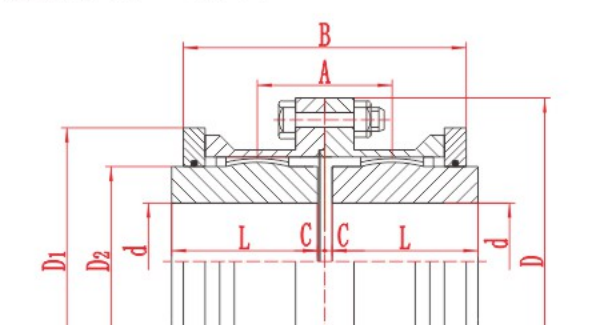
A full gear coupling has two flexible gear meshes, one at each end. A half gear coupling, often called a flex-rigid coupling, has one flexible gear mesh and one rigid connection. When a purchase order says “half gear coupling”, check the drawing and the scope of supply. The term can also refer to a single flexible half sold as a component.
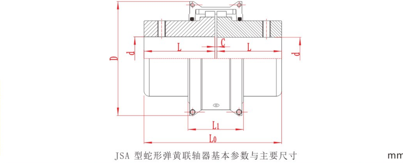
Use the same torque history, installation dimensions and maintenance constraints to compare gear and grid couplings for a shock-loaded drive.
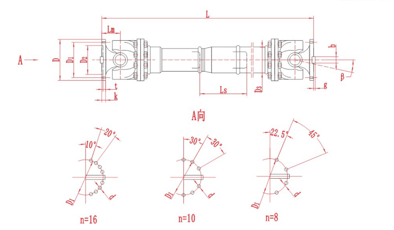
Use shaft-speed vibration data, joint-angle measurements and the approved drive tolerances to investigate vibration in an industrial Cardan shaft.

Identify angular, parallel and axial misalignment. Learn how to measure each one and check the installation tolerance for a flexible coupling.
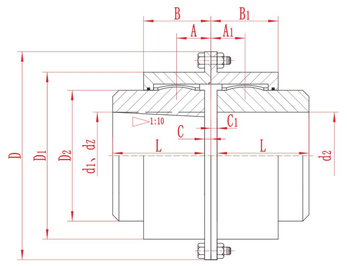
Before operating a gear coupling, confirm the approved lubricant, the fill quantity and units, the filling method and the next service interval for the exact model. Inspect the seals and plugs, then confirm whether the coupling was filled during asse
To confirm a gear coupling installation gap, identify the series, size and assembly arrangement. Use the approved drawing or installation manual to find the specified distance, the two faces it is measured between and its tolerance. Record the actual
Choose a jaw coupling spider by matching the coupling series, size and insert profile first. Then confirm the specified material and hardness for the operating duty. The spider is the resilient insert between the two hubs. Shaft bore and coupling out

An elastomeric coupling connects two rotating shafts and transmits torque through a resilient element. Jaw couplings use a spider between the hubs, tyre couplings use a flexible ring, and some pin couplings use resilient bushes or sleeves. In industr
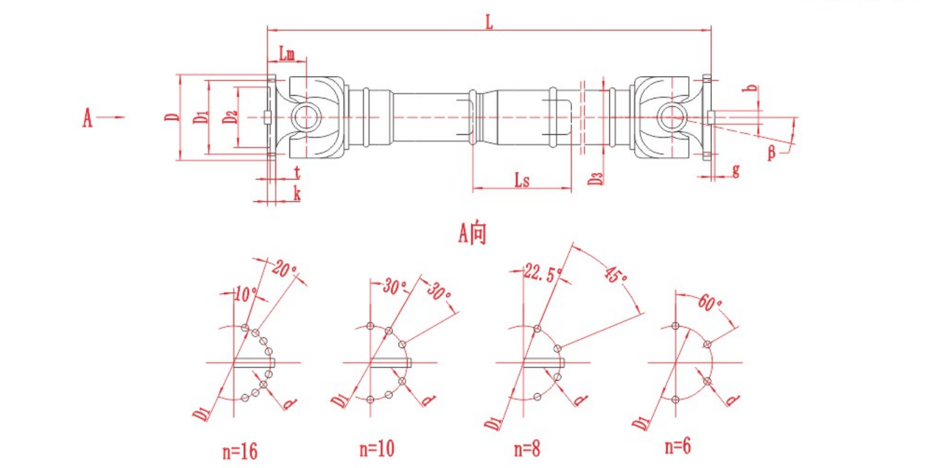
A Cardan shaft transmits torque between machines whose shaft axes are at an angle to the intermediate shaft. A typical industrial assembly has a universal joint at each end, an intermediate member and two machine connections. A telescopic version add
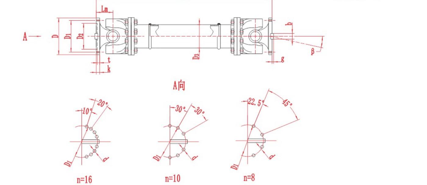
A universal joint coupling transmits rotation and torque between shafts that meet at an angle. In a cross-type joint, two fork-shaped yokes pivot on a four-armed cross. The joint can transmit torque while it articulates, but a single joint at a nonze
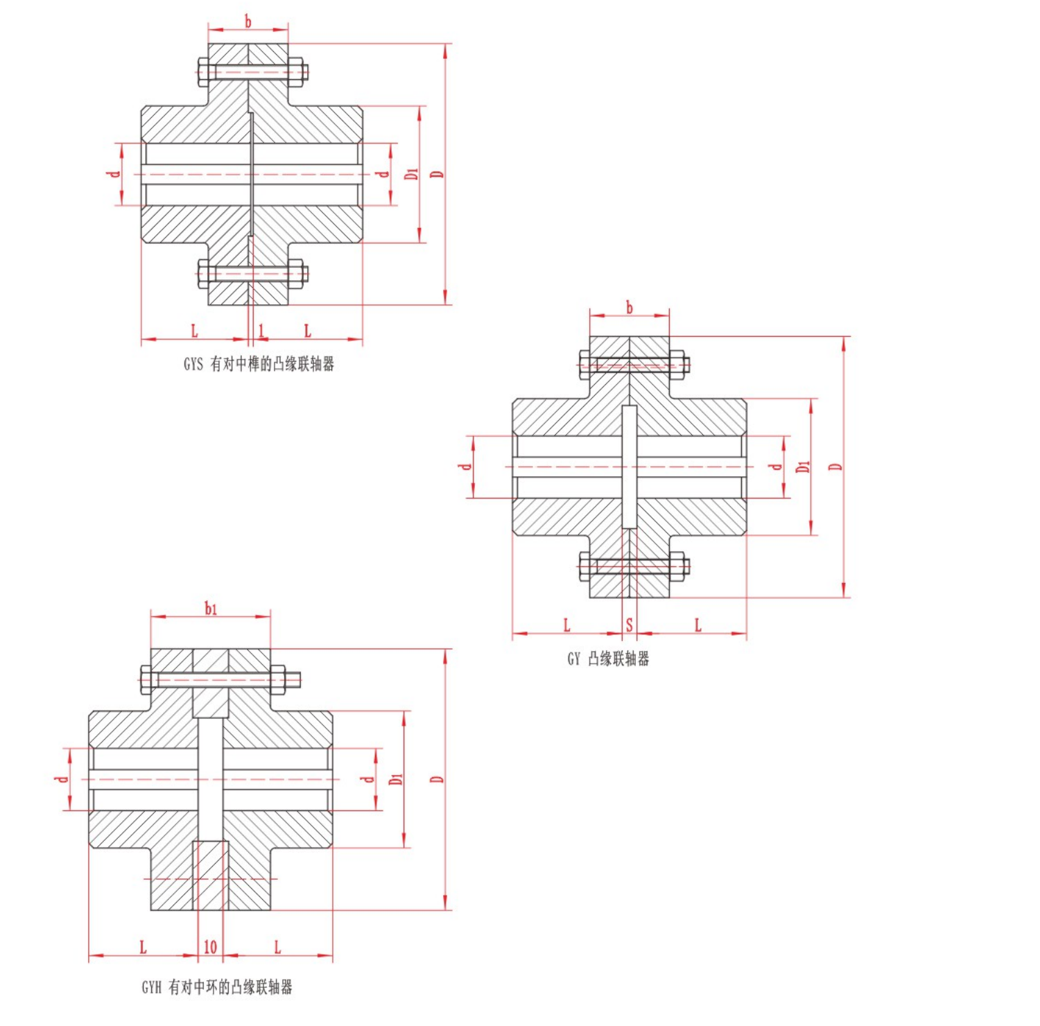
A shaft flange coupling transmits torque between two rotating shafts through flanges bolted together at their faces. In a rigid design, each flange is attached to its shaft and the bolted joint holds the two halves together. The machine must keep the
Send torque, speed, shaft and installation data for a preliminary review.