Technical Resources
How can a maintenance team investigate vibration in an industrial cardan shaft?
Use shaft-speed vibration data, joint-angle measurements and the approved drive tolerances to investigate vibration in an industrial Cardan shaft.
When an industrial Cardan shaft starts to vibrate, record the shaft speed, machine load and vibration at the bearings on both sides of the drive. Compare those readings with a baseline taken under similar conditions. During an isolated shutdown, measure the true operating angle at each universal joint and check the yoke phasing, flange seating and shaft condition. A peak at twice shaft speed gives the team a reason to check joint geometry and phasing, alongside other possible sources in the drive train. Experimental study of second-order Cardan-joint vibration
1. Capture the vibration before moving the machine
If the drive can run within site operating limits, collect data with guards in place, using installed sensors or approved measurement points on stationary bearing housings. If vibration rises sharply or a guard is rubbing, follow the site's shutdown procedure. Before removing a guard, touching the shaft or setting up alignment tooling, isolate and verify all hazardous energy sources under the site procedure. Support the shaft before releasing its fasteners. HSE guidance on safe machinery maintenance
Log the speed of the Cardan shaft itself. Motor rpm can be different when a gearbox lies between the motor and the shaft. Record the load, operating temperature or warm-up state, and machine position. If a rolling-mill spindle changes angle as the roll gap changes, record the roll position with each vibration reading.
Use the same sensor points and directions for repeat measurements. Where accessible, record horizontal, vertical and axial readings on the stationary housings nearest each end of the shaft. Save the time waveform and spectrum. For a variable-speed drive, use a speed reference and order tracking so you can tell which peaks follow shaft rpm. At a hypothetical shaft speed of 600 rpm, 1× is 10 Hz and 2× is 20 Hz. Those frequencies identify orders for that running condition. Acceptance limits come from the machine's approved criteria.
| Observation | What to check next |
|---|---|
| A strong 1× component follows Cardan shaft speed | Check for flange or pilot seating problems, runout and signs of damaged or missing balance weights. Check the adjacent machine for another source at the same frequency. |
| A strong 2× component appears after spline or yoke work | Verify both true joint angles, their planes and the specified phase marks. Compare readings at the two machine ends and check for overlapping speeds from other components. |
| Impacts, heat or noise are concentrated near one end | Under isolation, inspect the universal joint, nearby bearings and flange fasteners. Check play, lubrication condition and wear using the approved service procedure. |
| A peak rises in a narrow speed band, or with a particular load or roll position | Compare readings across approved operating points. Check whether the geometry shifts with position or load and have the team assess possible resonance or process excitation. |
Treat these patterns as leads. Corroborate the spectrum with physical measurements and the maintenance history before choosing a correction.
2. Measure both joint angles and verify yoke phasing
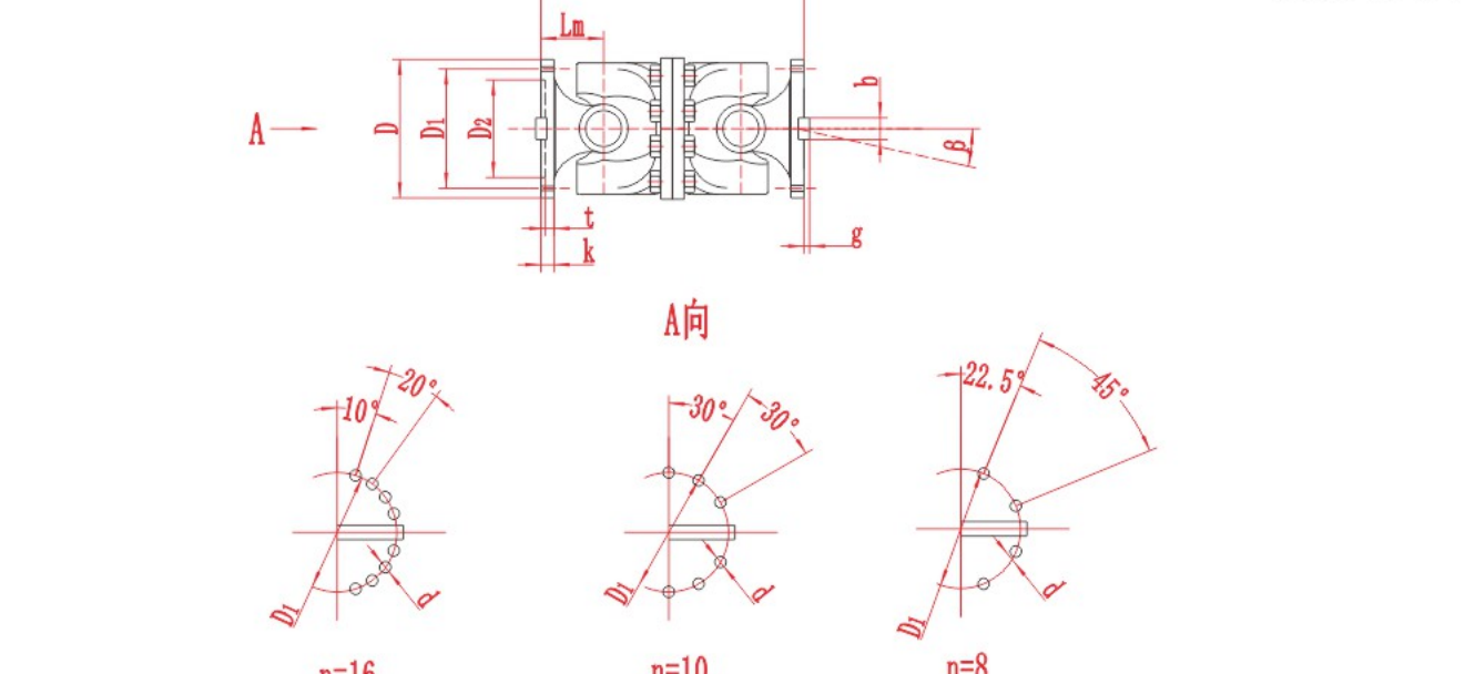
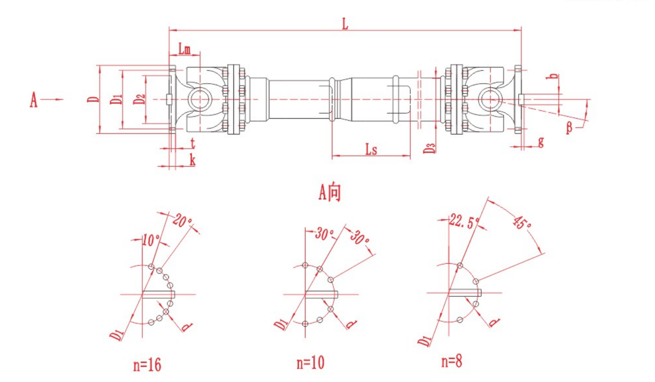
The true operating angle at each joint is the angle between the Cardan shaft axis and the connected machine shaft axis. Measure the driver, Cardan shaft and driven axes using the approved datums and a method suited to the layout. If there is offset in both the vertical and horizontal planes, determine the true three-dimensional joint angles from the axis measurements. A single side-view reading can miss part of the angle.
In a conventional coplanar two-joint layout, equal true operating angles and the specified yoke phase allow the second joint to cancel the first joint's cyclic speed variation at the output in ideal geometry. The intermediate shaft still sees cyclic speed variation. Use the assembly drawing for compound-angle layouts, multiple shafts or intentional out-of-phase arrangements. University study of Cardan joint arrangement and speed variation
Verify the yoke orientation against the drawing and match marks, particularly if someone separated the sliding spline during an overhaul. Photograph marks and record the as-found angles before adjusting machine feet or refitting the shaft. A laser setup for an offset drive must use the references and fixtures specified for that geometry.
3. Find the Cardan shaft alignment tolerances for the installed drive
Cardan shaft alignment tolerances depend on the shaft model, the machine layout and the operating duty. Start with the machine builder's alignment specification and the approved shaft drawing or service manual. Ask the responsible engineer or manufacturer to resolve missing or conflicting limits before accepting the drive for service. A catalogue operating-angle limit describes the joint's articulation under its stated conditions. The permitted end-to-end angle difference, flange runout, yoke phase and vibration each need their own acceptance criterion.
| Check | Record | Where to get the limit |
|---|---|---|
| Driver and driven joint geometry | True angle at each end in degrees, angle difference if specified, measurement planes and machine position | Approved layout and shaft application data for the actual speed, torque and duty |
| Yoke phasing | Match-mark or yoke orientation, with phase angle in degrees if specified | Assembly drawing or shaft service instruction |
| Flange, pilot and runout | Seating condition and radial and face total indicator readings in mm at specified datums | Machine and shaft flange drawings or installation instructions |
| Telescopic travel, where fitted | Installed, minimum and maximum working lengths in mm from the same datums | Drawing limits for usable travel and spline engagement |
| Machine vibration | Sensor point, direction, amplitude, units and operating condition | Site or machine acceptance criteria and the applicable measurement standard, where specified |
A drive can have intentional parallel offset. Compare measured geometry with the approved layout before changing shims or machine position. A vibration value in mm/s is meaningful for acceptance only with the specified location, measurement convention and operating condition. ISO 20816-1 measurement and evaluation scope
4. Inspect, correct and retest
With the drive isolated, inspect flange faces and pilots for debris, fretting or damage. Check fastener condition, joint play and lubrication against the service instructions. On telescopic shafts, look for spline binding or wear and verify that working length stays within the approved travel throughout the machine's operating range. Record suspected tube damage or lost balance weights and refer the assembly for qualified runout or balance assessment before making changes to it.
After correcting a verified defect, record what changed and repeat measurements with the guards restored and the drive released for the test. Compare the same sensor points, speeds, loads and machine positions with the as-found readings. Record the before-and-after spectra and the measured geometry, then apply the site's restart and acceptance criteria. If the original peak remains, include the gearbox, bearings, foundation and process excitation in the follow-up investigation.
If you need an engineering review of a RONGXING DRIVE shaft, send the model or drawing reference, latest spectrum with shaft rpm, both joint angles, phase-mark photos, flange runout and installed length. For a telescopic unit, include the shortest and longest working positions. Note any work done shortly before the vibration began. Industrial Cardan shaft replacement drawings and checks