
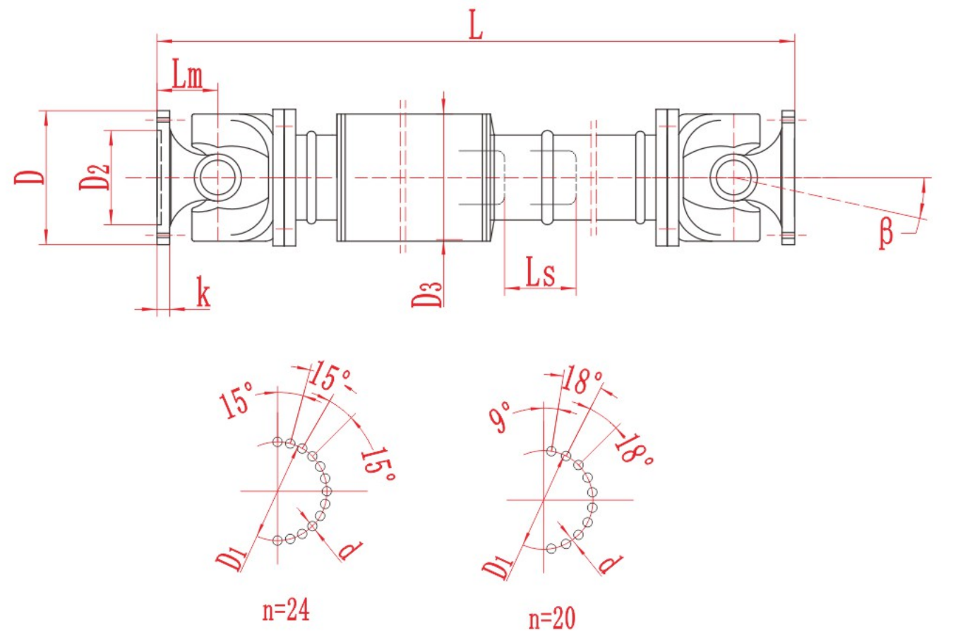
Large SWC-BF Telescopic Flanged Cardan Shaft
Large SWC-BF Telescopic Flanged Cardan Shaft with technical data and assembly drawing for preliminary selection.
View Large SWC-BF Telescopic Flanged Cardan Shaft DetailsCurated technical topic
Couplings can accommodate defined angular, radial or axial displacement, but they are not a substitute for alignment work. Identify the direction and magnitude of movement at the coupling and distinguish static installation error from movement during operation.
The product table and drawing should be read together: a stated displacement value may depend on speed, lubrication, temperature or the selected size. Share measured or calculated movement in the inquiry.
Not necessarily. Capacity can affect stiffness, bearing loads, heat and service life. Select the smallest structure that safely covers the actual movement and duty.
Large SWC-BF Telescopic Flanged Cardan Shaft with technical data and assembly drawing for preliminary selection.
View Large SWC-BF Telescopic Flanged Cardan Shaft Details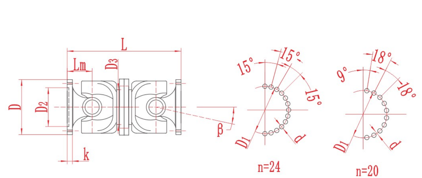
Large SWC-WD Non-Telescopic Short Cardan Shaft with technical data and assembly drawing for preliminary selection.
View Large SWC-WD Non-Telescopic Short Cardan Shaft Details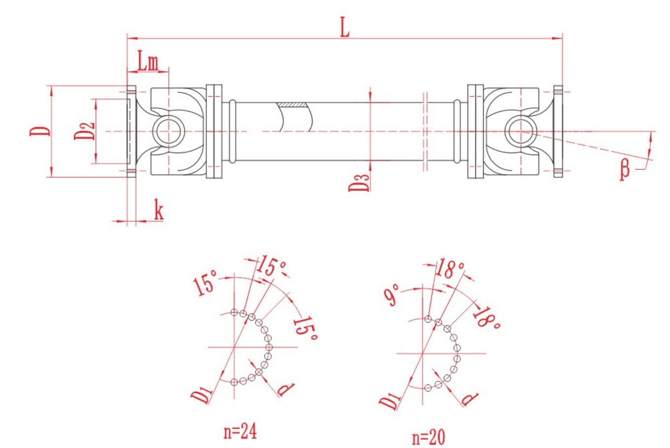
Large SWC-WF Non-Telescopic Flanged Cardan Shaft with technical data and assembly drawing for preliminary selection.
View Large SWC-WF Non-Telescopic Flanged Cardan Shaft Details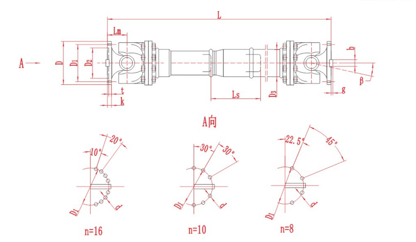
SWC-BF Telescopic Flanged Cardan Shaft with technical data and assembly drawing for preliminary selection.
View SWC-BF Telescopic Flanged Cardan Shaft Details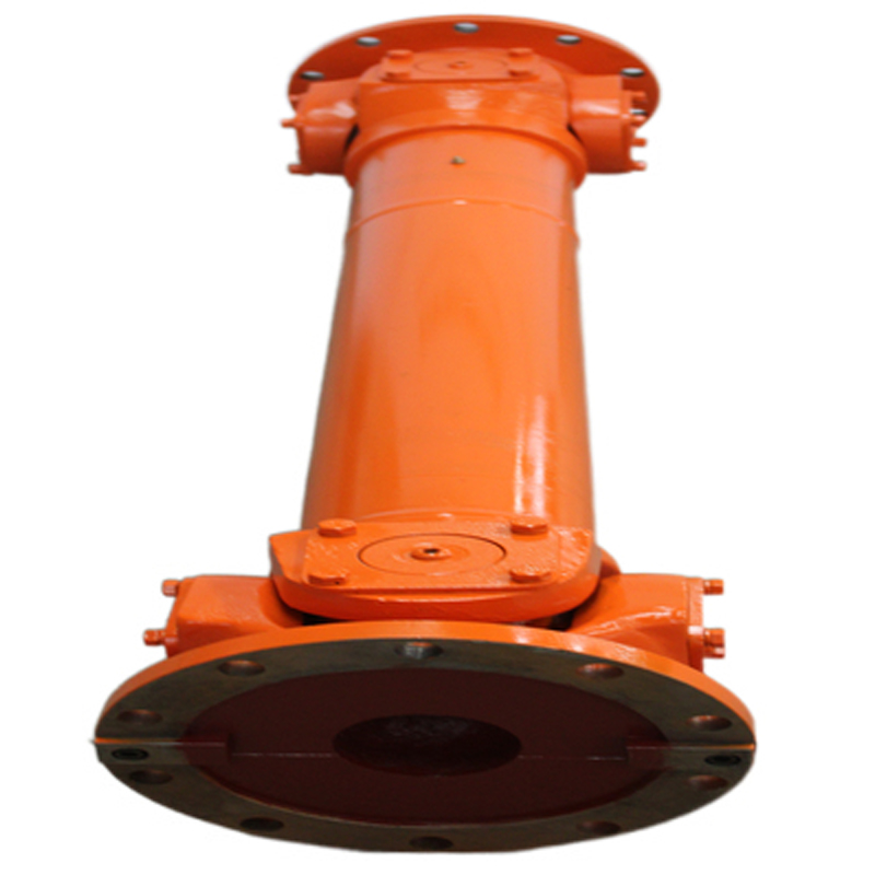
SWC-CH Long Telescopic Welded Cardan Shaft with technical data and assembly drawing for preliminary selection.
View SWC-CH Long Telescopic Welded Cardan Shaft Details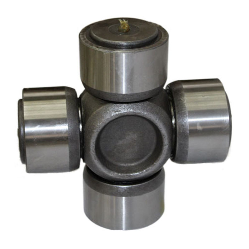
SWC-DH Short Telescopic Welded Cardan Shaft with technical data and assembly drawing for preliminary selection.
View SWC-DH Short Telescopic Welded Cardan Shaft Details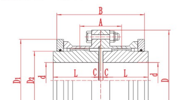
A full gear coupling has two flexible gear meshes, one at each end. A half gear coupling, often called a flex-rigid coupling, has one flexible gear mesh and one rigid connection. When a purchase order says “half gear coupling”, check the drawing and the scope of supply. The term can also refer to a single flexible half sold as a component.

Use shaft-speed vibration data, joint-angle measurements and the approved drive tolerances to investigate vibration in an industrial Cardan shaft.

Identify angular, parallel and axial misalignment. Learn how to measure each one and check the installation tolerance for a flexible coupling.
To confirm a gear coupling installation gap, identify the series, size and assembly arrangement. Use the approved drawing or installation manual to find the specified distance, the two faces it is measured between and its tolerance. Record the actual
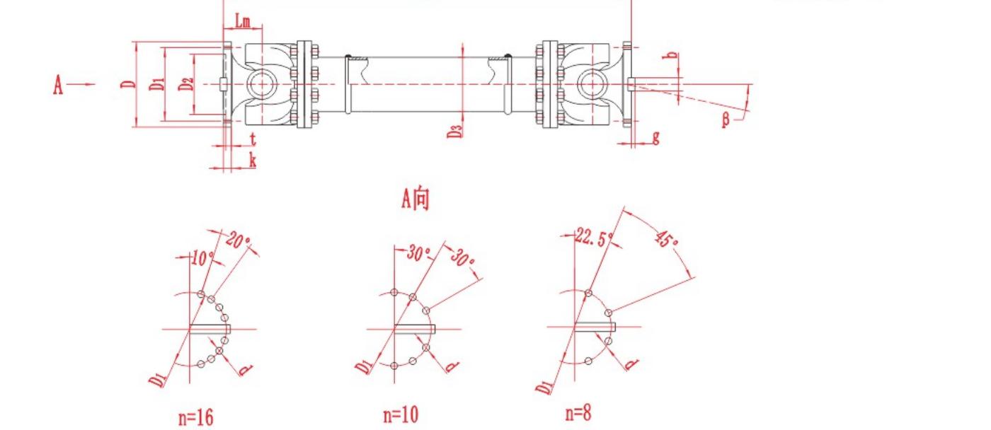
A universal joint coupling transmits rotation and torque between shafts that meet at an angle. In a cross-type joint, two fork-shaped yokes pivot on a four-armed cross. The joint can transmit torque while it articulates, but a single joint at a nonze
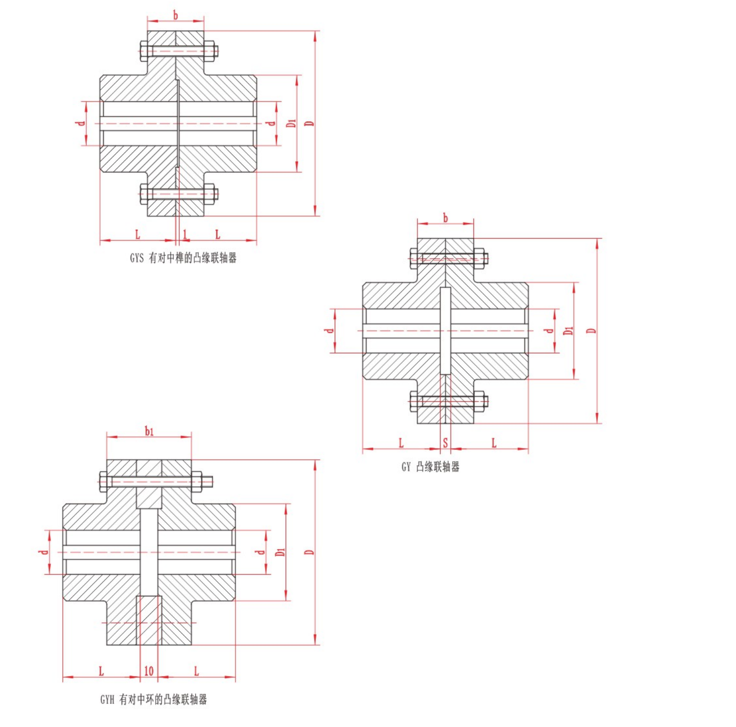
The two main types of mechanical shaft coupling are rigid and flexible. A rigid coupling joins shafts without a flexible element and depends on the required alignment being maintained. A flexible coupling accommodates limited movement within the limi
Topic FAQ
Angular misalignment is an angle between shaft axes; parallel misalignment is an offset between otherwise parallel axes; axial movement changes the distance along the shaft direction. Record each separately because the selected coupling may have different limits for each mode. Record the three movement modes with the other shaft movement data for coupling selection.
No. A coupling accommodates specified residual or operating movement after proper alignment. Excessive misalignment can increase loads and wear. Check installation alignment and expected thermal movement against the limits for the actual model. For a cardan configuration, consult the industrial cardan shaft selection guide alongside the actual shaft layout.
Do not assume so. Published limits may apply under different conditions, and combined displacement can reduce the allowable operating range. Submit the simultaneous movements, torque and speed for a model-specific review.
Send torque, speed, shaft and installation data for a preliminary review.