Technical Resources
What flange and bolt-pattern dimensions are needed before ordering an industrial cardan shaft?
Before ordering an industrial cardan shaft, record both flange diameters, pilot fits, bolt circles, hole sizes and clocking. Use the drawing checklist.
Provide a dimensioned end view and section for each mating flange before ordering an industrial cardan shaft. Record the flange outside diameter and thickness, pilot or register diameter and depth, bolt pitch circle diameter (PCD), hole count, hole size and angular positions. Mark threaded holes and show any face key, teeth or dowels. Label the drive and driven ends separately, even when they look alike.
For a plant in India, state the units on both drawings. If an existing drawing uses inches, keep the original dimensions and thread callouts alongside any metric conversions. Record the drawing number and revision so the supplier can identify the interface being quoted.
What to record on each flange drawing
Use the mating face and flange axis as drawing references. Mark the viewing direction on the end view because looking from the back can reverse the apparent position of an offset hole or key.
| Feature | What to give the supplier |
|---|---|
| Flange body | Outside diameter, thickness at the bolt seats, mating face and any step or recess that affects seating or clearance |
| Pilot or register | Male spigot or female recess, diameter, projection or recess depth measured from the mating face, and the specified fit or tolerance |
| Bolt circle | PCD, hole count on each circle and whether the holes are evenly spaced |
| Hole details | Clearance hole diameter or thread designation and pitch, usable thread depth for blind holes, plus any counterbore or spotface required by the drawing |
| Angular position | Hole angles or centre coordinates, direction of measurement and a reference such as a face key, dowel or marked datum |
| Torque transfer and locating features | Dimensions and orientation of any face key, cross key, teeth, serrations or dowels shown on the approved connection |
| Hardware and access | Approved bolt, nut and washer specification where applicable, available space behind the flange and the access needed to insert and tighten the fasteners |
Use the end view for the pattern and its orientation. Use the section view for the pilot, axial dimensions and hole depth. Mark tolerances and drawing datums where they are known. For a replacement, keep measurements of worn holes or registers separate from the required dimensions for the new assembly.
How to record the bolt pattern
PCD is the diameter of the circle through the hole centres. Record the diameter of the holes separately from the bolt size. For tapped holes, identify the thread system, nominal size and pitch from the drawing or verified thread identification. A clearance hole diameter alone cannot establish the approved bolt specification.
For an evenly spaced circular pattern with a pair of diametrically opposite holes, their centre-to-centre distance is the PCD. If only adjacent centres are accessible, use the following relationship to cross-check a confirmed single circle of equally spaced holes.
PCD = c / sin(180° / n)
Here, c is the straight-line distance between adjacent hole centres, n is the number of equally spaced holes on that circle and the angle is in degrees. If c is in mm, the result is in mm. In a hypothetical pattern with six equally spaced holes and 75 mm between adjacent centres, the PCD is 150 mm.
For paired, offset or unequally spaced holes, provide the angles or coordinates from a common datum. For multiple bolt circles, identify which holes belong to each circle. A face key or dowel makes the relationship between the pattern and the locating feature part of the fit. The approved drawing is the reference for nominal dimensions and tolerances.
How to read the SWP-E flange example
The RONGXING DRIVE SWP-E telescopic double-flange long cardan shaft illustrates how the hole pattern and the flange diameters are specified separately. The catalogue distinguishes swing diameter D from the other flange dimensions. Its n-d entry describes hole count and diameter, and the flange views show the layout for different hole counts. Select the exact model row and compare the relevant flange view with the drawing for each mating part.
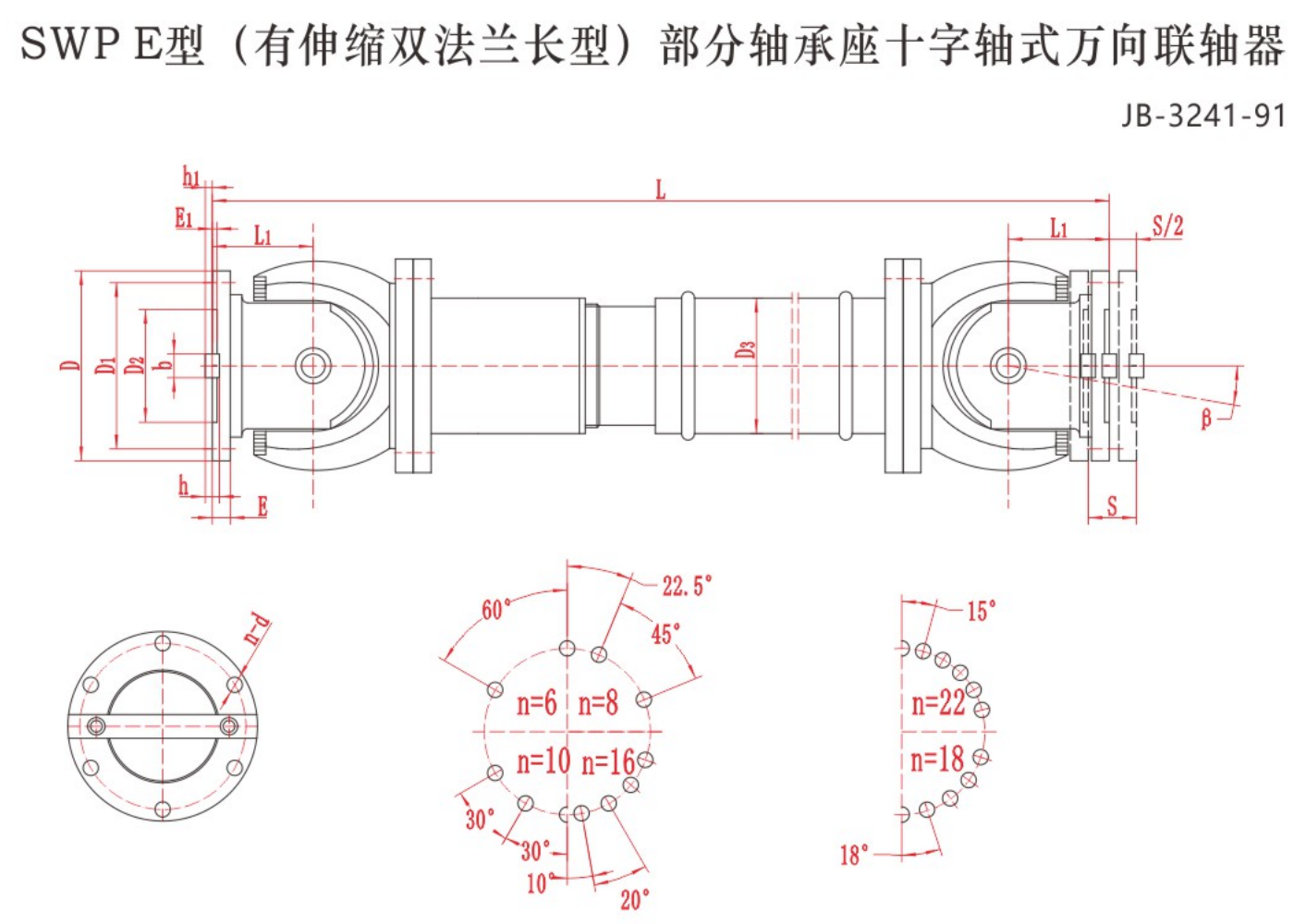
SWP-E catalogue drawing. The angles in the flange end views locate holes. The β symbol in the assembly view identifies the shaft operating angle. Use the approved model drawing for the connection dimensions and tolerances.
Check the pilot diameter and fit, the mating depth and any face feature before approving the flange. A male pilot and its mating recess must seat as intended at the specified face. Measure the features from that face so the supplier can compare the available depth with the pilot projection. Compare the hole positions with the mating part in its approved orientation.
Pipe flange tables cover a different application. If a drawing or purchase request names a standard, record its exact designation and confirm it applies to the specified driveline interface. ASME lists B16.5 under pipe flanges and flanged fittings. ASME standards scope
What to approve before placing the order
When measuring installed equipment, follow the site’s isolation and stored energy procedures and have competent personnel support any assembly that could move or fall. The UK Health and Safety Executive describes the general principles for safe maintenance planning. Maintenance guidance
Send both mating flange drawings or dimensioned surveys, with photographs as identification aids. Identify the equipment and shaft position. Mark any interface modifications or restrictions on bolt access. If an adapter is part of the proposal, include its machine-side and shaft-side interfaces in the drawing review.
Ask for the proposed shaft drawing and compare it with both machine interfaces before ordering. Confirm the fastener specification and assembly procedure for that connection with the responsible engineer or supplier. Use the instructions for the approved hardware and joint when checking tightening requirements.
Complete the shaft review with the installed face-to-face length, any movement or travel, joint angles and the actual torque and speed duty. The flange drawings establish fit at the interfaces. The supplier needs the operating data to assess the complete shaft. See the cardan shaft quotation data guide for Indian buyers and the replacement drawings and checks guide.
For a RONGXING DRIVE proposal, send the two end drawings and operating data. Identify any missing dimensions so they can be resolved before the drawing becomes the order specification.
Frequently asked questions
Is the flange diameter and number of holes enough?
Provide the PCD, hole diameter or thread, hole positions, pilot dimensions and locating features as well. The outside diameter and hole count can match while the bolt circles or pilot fits differ.
Can I specify the same flange at both ends?
Yes, if the two mating interfaces are confirmed to be identical and the proposed drawing shows the correct orientation at each end. List each end separately so the supplier can check it against the corresponding machine connection.
Can I measure PCD from the outside edges of two holes?
Measure between hole centres. A distance measured between edges depends on the hole diameters and the edges chosen. If the holes are worn or the layout is unclear, verify the nominal pattern from a drawing or a suitable dimensional survey before committing to the order.