Technical Resources
What torque, speed, angle and installed-length data should an Indian buyer provide for a cardan shaft quotation?
Prepare a cardan shaft quotation request for India with torque, rpm, joint angles, installed lengths and flange drawings. Includes a practical RFQ checklist.
For a cardan shaft quotation, an Indian buyer should providenormal and peak torque with the load cycle; minimum, normal and maximum speed at the shaft; the angle at each joint through the operating positions; and the normal, shortest and longest installed connection distances with defined measurement references. Add drawings of both connections, the application, environment, quantity and delivery destination. Identify estimated or missing values so that a preliminary quotation is not mistaken for a confirmed selection.
The four headline parameters must describe the same installation. A motor nameplate, a photograph and one overall length usually leave important questions unanswered.
The four data groups to include in your enquiry
| Data group | What the buyer should provide | Units and context |
|---|---|---|
| Torque | Normal operating torque; starting, braking and other peaks; event duration, frequency and reversals | N·m or kN·m, identified at the cardan shaft |
| Speed | Minimum, normal and maximum speed; variable-speed range; starts and stops | r/min (rpm), at the same shaft location as the torque data |
| Angle | Angle at the driving-end joint and driven-end joint; normal and extreme positions; plan and elevation views | Degrees (°), with each machine position identified |
| Installed length | Normal, minimum and maximum connection distances; measurement reference planes; separate assembly/removal movement | mm, with required working travel distinguished from catalogue length compensation |
Use one unit system throughout the enquiry. 1 kN·m = 1,000 N·m. State whether each value comes from a drawing, measurement, calculation, equipment specification or an estimate.
1. Torque: explain the load, not just the largest number
Provide the torque transmitted at the proposed cardan shaft location. Include the driven machine, the shaft’s position in the drivetrain and whether operation is continuous, intermittent or cyclic.
Separate the normal load from events such as starting, material biting, braking, reversing or a process overload. For each important peak, give its magnitude, duration and frequency where known. If a torque limiter or drive protection setting is relevant, identify the setting and its basis; do not present it as a measured shaft load.
For example, “peak torque occurs once per shift during starting” describes a different duty from “the same peak occurs every few seconds during production.” A single peak figure does not describe repeated loading.
If torque is unknown, provide power and speed at the shaft
For a steady operating point, the transmitted torque can be calculated from mechanical shaft power:
T (N·m) = 9,550 × P (kW) / n (r/min)
Here, P is the mechanical power transmitted at the cardan shaft and n is its rotational speed. Motor electrical input power is not automatically the transmitted mechanical shaft power. Where a gearbox lies upstream, state the ratio and identify which values refer to its input and output.
This relationship does not establish starting torque, stall torque or transient peaks. It is not valid for calculating torque by dividing by zero speed. With variable-speed duty, provide the actual power or torque at each relevant speed rather than assuming constant power across the whole range.
The RONGXING DRIVE SWC-BH product table lists rated torque Tn and fatigue torque Tf separately. These are product rating fields, not alternative names for a buyer’s measured peak torque. The supplier must assess the actual duty against the proposed model’s rating definitions.
2. Speed: identify the shaft location and the operating range
State minimum, normal and maximum cardan shaft speed, including any relevant idling or test condition. Indicate whether a variable-frequency drive, gearbox or changing production setting alters the speed. Add start/stop frequency and whether the drive reverses.
Avoid sending motor rpm alongside output-shaft torque without identifying the reduction. A dimensioned drivetrain sketch makes the data easier to interpret.
For a long shaft or a wide speed range, provide the shaft layout and support arrangement so that the supplier and machine engineer can determine the necessary dynamic assessment. Request confirmation of balancing and permissible operation for the proposed assembly. Do not select a balancing grade from maximum rpm alone.
3. Angle: describe both joints and the machine positions
Record the angle between the cardan shaft centreline and the connected equipment axis at each universal joint. Use clear labels such as driving-end joint and driven-end joint; do not give only the angle between the two machines’ axes.
For moving equipment, identify the angles in the normal position and at the relevant extremes. Where offsets occur horizontally and vertically, provide plan and elevation views, or a dimensioned three-dimensional layout. Horizontal and vertical angle components should not simply be added to claim the actual joint angle.
Include existing phasing marks or assembly information for a replacement. Final joint arrangement and phasing require review of the complete geometry; do not prescribe a universal fork orientation from a photograph alone.
An angle value is meaningful only with its operating condition. A large angle used during a disconnected maintenance position is not the same requirement as that angle occurring while transmitting torque at maximum speed. Mark which positions are connected, rotating and loaded.
4. Installed length: define the measurement references
Give the distance between the agreed connection reference planes at normal operation and at the shortest and longest connected working positions. For a flanged installation, identify the relevant mating faces on the drawing; do not assume that every supplier uses the same definition of overall length.
Distinguish three quantities:
Installed connection distance: the space the assembly must fit at a stated equipment position.
Required working movement: the change in connection distance during connected operation.
Available length compensation: a property of the proposed shaft, subject to its permitted installed position and engagement limits.
The fully compressed length of an old shaft does not, by itself, specify its installed working length. Do not extend or compress an existing assembly beyond its approved limits to obtain measurements. Follow the plant’s isolation and measurement procedures.
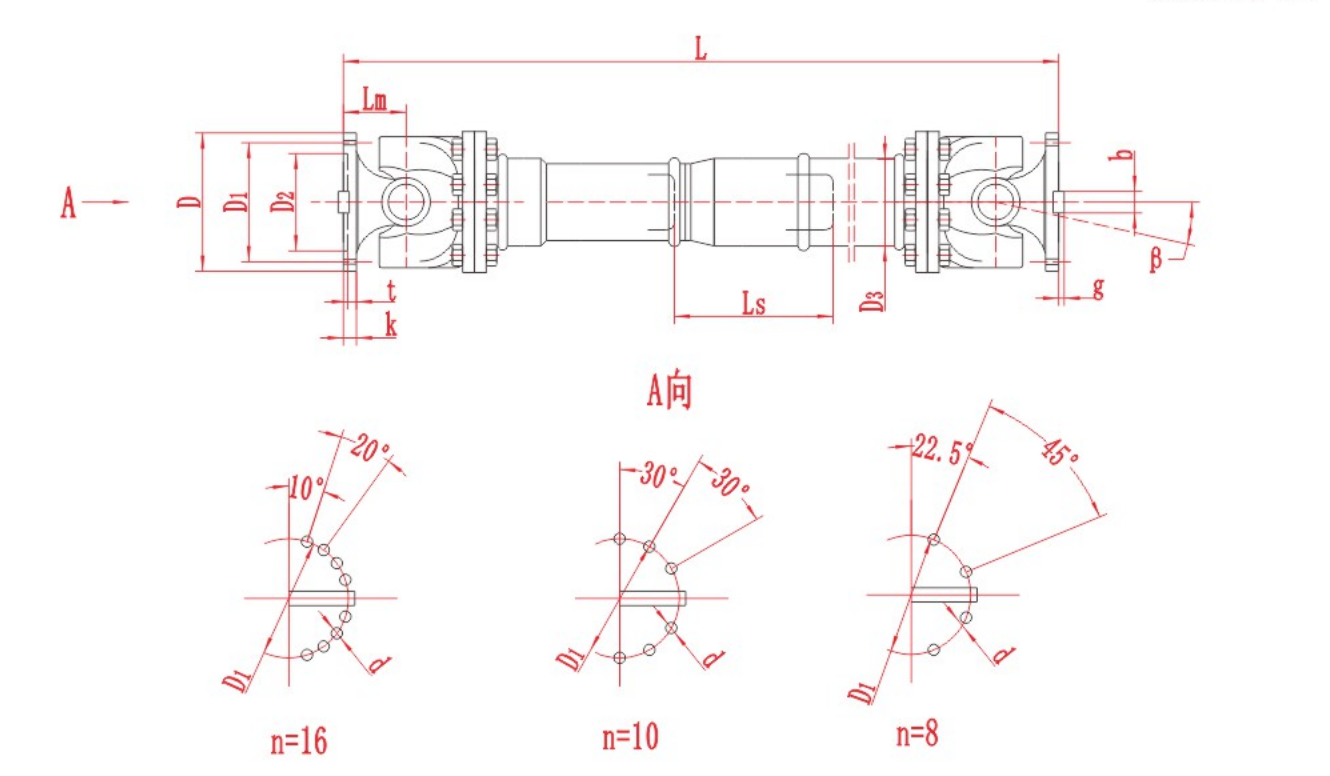
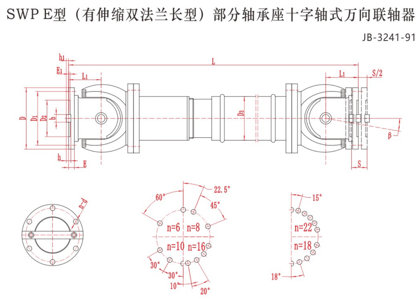
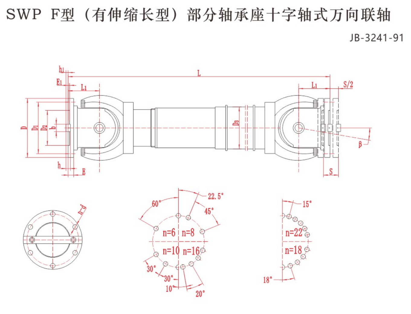
Figure 1. RONGXING DRIVE SWC-BF assembly drawing. Read L, Ls and β with the matching model table and agreed drawing definitions. The lower diagrams show flange-hole arrangements; their angular markings are not operating-angle limits.
Provide assembly and removal space separately from working travel. The supplier should confirm spline engagement, clearance against bottoming, extension limits and the intended installed position. Enough total travel does not prove that enough travel remains in each direction.
A hypothetical operating-point example
The following data illustrates how to organise an enquiry. It is not a tested installation or a recommendation for a RONGXING DRIVE model.
| Condition | Shaft load and speed | Joint angles | Connection distance |
|---|---|---|---|
| Normal production | 110 kW mechanical shaft power at 300 r/min | 4° driving end; 4° driven end | 1,200 mm between identified mating faces |
| Connected adjustment limits | Load and speed during adjustment still to be supplied | Range at each joint still to be supplied | 1,180–1,220 mm between the same faces |
| Starting/braking | Peak torque, duration and frequency still to be supplied | Geometry at those events to be confirmed | Position during those events to be confirmed |
At the stated normal point, T = 9,550 × 110 / 300 ≈ 3,502 N·m = 3.50 kN·m. The connection-distance range is 40 mm, with 20 mm of movement either side of the stated normal distance.
Neither calculation determines the final shaft size. The missing peak loads, simultaneous angle/speed conditions and connection details still require review. A catalogue listing 40 mm of travel would not, on that fact alone, establish suitability.
5. Add both connection drawings and the site requirements
The four core data groups are not a complete purchasing specification. Attach drawings for both ends, including locating features and fits, bolt-circle diameter, hole count and diameter, and the actual torque-transfer interface. Include the rotating envelope, guard clearance and access for installation and lubrication.
For a replacement, add the existing identification, photographs, drawing revision and reason for replacement. An old part number helps identify a configuration; it does not prove that the previous selection suited the duty.
For an Indian project, state the actual delivery city or plant and the purchasing contact. Record temperature near the shaft, dust, scale, water or chemical exposure, operating hours and maintenance opportunities. Country alone does not specify a grease, sealing arrangement, inspection requirement or local service commitment.
List the quantity, requested delivery date, documentation and inspection requirements. Price, availability, delivery terms and technical acceptance should be confirmed for the particular enquiry.
6. Send a consistent RFQ data sheet to RONGXING DRIVE
Use the following checklist as the structure of your enquiry. Mark unknown values as not yet measured or not yet confirmed, rather than entering zero.
| RFQ field | Information to enter |
|---|---|
| Application and shaft position | Driving equipment, driven equipment, industry and gearbox arrangement |
| Torque and duty | Normal torque, peaks, duration, frequency, reversing and operating hours |
| Power and speed | Mechanical shaft power; minimum, normal and maximum rpm; variable-speed conditions |
| Joint geometry | Driving-end and driven-end angles by position; plan/elevation drawing |
| Working length | Normal, shortest and longest connection distances with reference planes |
| Travel and handling | Working movement, assembly/removal allowance and available access |
| Connections | Both mating drawings, pilot/fit, bolt pattern and interface details |
| Environment | Temperature, contamination, exposure and maintenance access |
| Replacement information | Existing model/marking, photographs and failure or replacement reason |
| Commercial and document needs | Quantity, destination in India, requested date, specifications and inspection records |
A telescopic configuration such as SWC-BHor SWC-BFmay enter the comparison where operating geometry requires length compensation. A series name does not establish the final size, speed capability, connection compatibility or suitability.
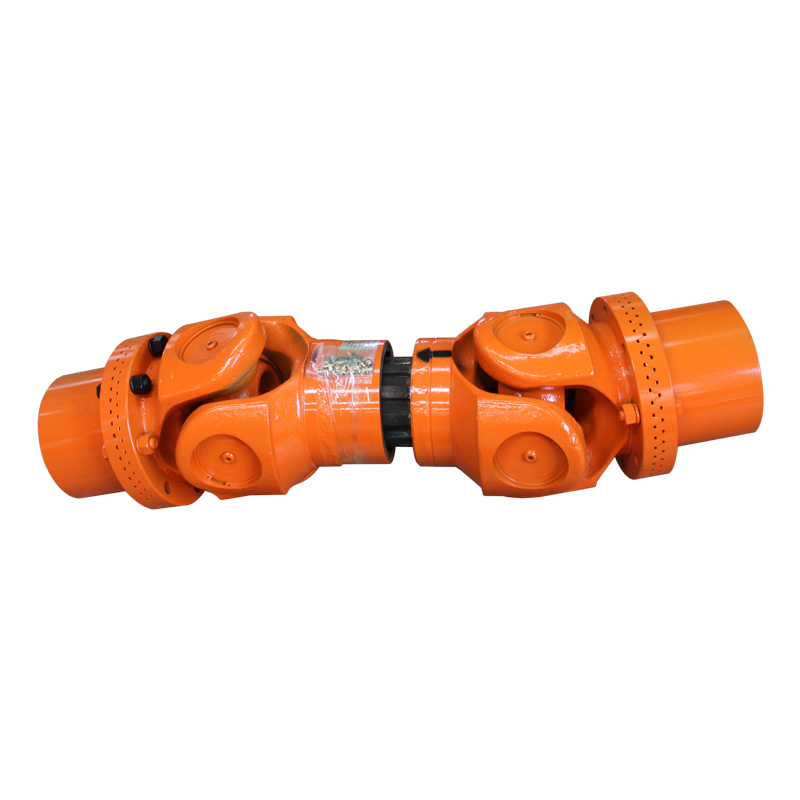
Figure 2. SWC-BH product assembly. This photograph identifies a configuration for discussion; use the proposed model’s own drawing and confirmed specification for quotation and acceptance.
The RONGXING DRIVE enquiry form accepts power/speed and operating/connection information. Paste the essential data into those fields and identify the drawings available for follow-up. A drawing or datasheet can be shared during the response; do not assume the form has a file-upload facility.
For the broader engineering process, see the industrial cardan shaft sizing guide. For stand-specific rolling duty, use therolling-mill cardan shaft selection guide for India.
Frequently asked questions
Can I request a quotation without knowing peak torque?
Yes. Send the available data, identify peak torque as unknown and describe starting, braking, reversing and shock events. Ask which additional inputs are needed and whether the quotation is preliminary. Do not treat an assumed peak as a verified operating load.
Is fully compressed length enough to specify a telescopic cardan shaft?
No. Supply the installed connection distance at normal and extreme working positions, using identified reference planes. The supplier also needs to confirm travel, engagement and assembly requirements for the proposed shaft.
Should I send maximum torque, maximum rpm and maximum angle as separate numbers?
Send those limits, but also explain which combinations actually occur. Use an operating-condition table so that a peak at low speed is not confused with continuous loading at maximum speed and angle.
Do Indian buyers need a different torque formula?
No. The power–torque relationship does not change with the delivery country. India-specific enquiry details concern the actual plant, destination, documentation and agreed purchasing requirements; mechanical selection follows the duty and geometry.