Technical Resources
Industrial Cardan Shaft Sizing and Universal Joint Shaft Selection
Industrial cardan shaft sizing involves checking load capacity, operating conditions and installation dimensions together. Universal joint shaft selection also requires a suitable shaft configuration, sufficient length compensation where needed, and compatible connections. This guide explains how to assess these requirements and prepare the information needed for a technical review of SWC and SWP cardan shafts.
Industrial cardan shaft sizing involves checking load capacity, operating conditions and installation dimensions together. Universal joint shaft selection also requires a suitable shaft configuration, sufficient length compensation where needed, and compatible connections. This guide explains how to assess these requirements and prepare the information needed for a technical review of SWC and SWP cardan shafts.
A cardan shaft connects rotating drive components through universal joints, allowing torque transmission between shafts operating at an angle. This article addresses complete industrial shaft assemblies, rather than automotive replacement joints or vehicle-specific driveshafts.
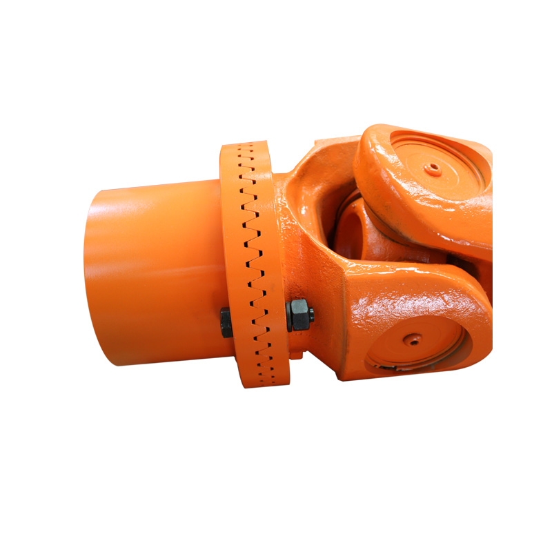
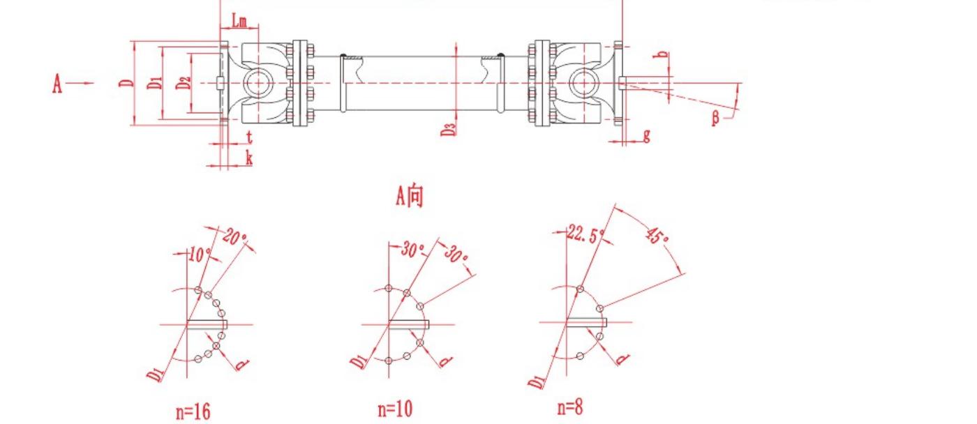
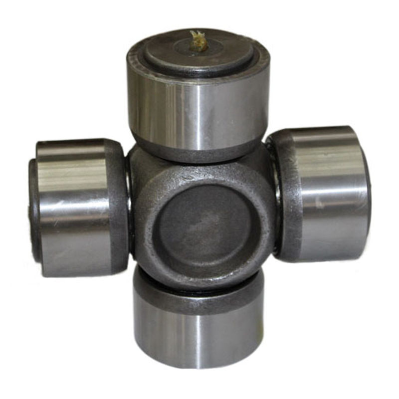
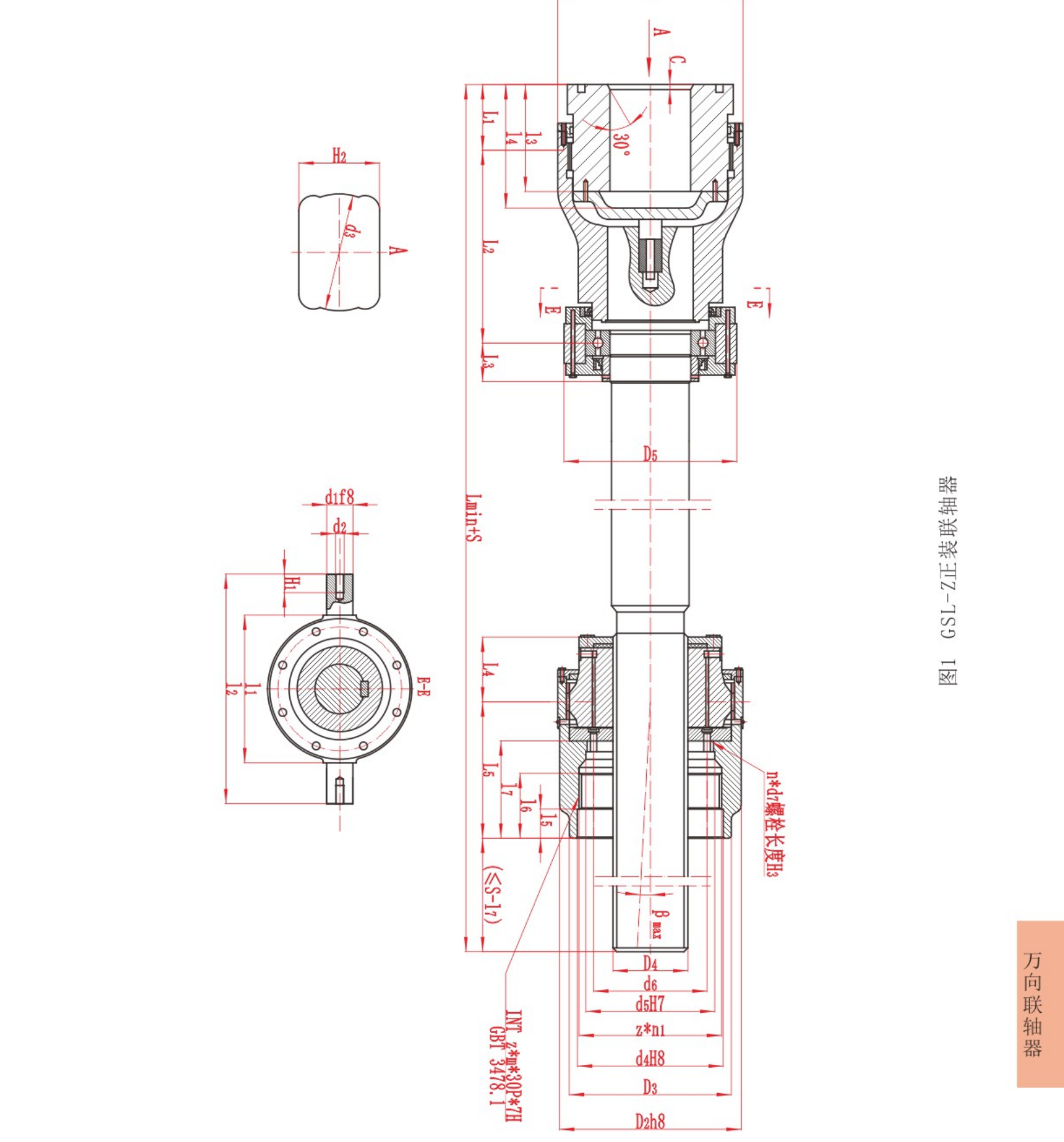
Figure 1. Joint and connection detail of the SWC-BH Telescopic Welded Cardan Shaft. Connection geometry and available clearance are part of the selection process.
What Does Cardan Shaft Sizing Involve?
Sizing is more than choosing a shaft diameter or matching a torque value. A suitable assembly must satisfy three groups of requirements:
Load capacity: transmitted torque, peak loads, reversing duty and repeated loading.
Operating conditions: shaft speed, joint angles, installation arrangement and operating environment.
Installation dimensions: shaft length, required axial movement, flange interfaces and rotating clearance.
A shaft that meets the nominal torque requirement may still be unsuitable if its installed length, operating angle or connection dimensions do not match the equipment.
The purpose of preliminary sizing is to identify suitable candidates and the checks needed before a final model is confirmed.
Collect the Operating and Installation Data
Start with information from the actual drive system. For replacement work, record both the existing shaft dimensions and the operating conditions. An existing shaft is a useful reference, but its dimensions alone do not establish whether it was correctly selected.
| Information | What to record | Why it matters |
|---|---|---|
| Transmitted power or torque | Mechanical power at the shaft, or measured operating torque | Establishes the initial load requirement |
| Shaft speed | Normal, minimum and maximum operating speed | Affects torque calculation and dynamic assessment |
| Load behaviour | Starting, stopping, shock loads, reversals and overload events | Identifies conditions not represented by steady torque |
| Operating duty | Running hours, load cycles and frequency of starts | Helps assess repeated loading |
| Joint angles | Angle at each joint and any change during operation | Defines the angular operating conditions |
| Installed length | Distance between the specified connection reference planes | Establishes the required assembly length |
| Length variation | Minimum and maximum connection distances during movement | Determines whether length compensation is needed |
| Connection details | Flange dimensions, locating features, bolt holes and mating drawings | Establishes interface compatibility |
| Available space | Clearance around the rotating assembly and access for installation | Helps prevent interference |
| Environment | Temperature, dust, moisture, corrosive exposure and maintenance access | Identifies additional requirements for technical review |
Use consistent units. Torque may be expressed in N·m or kN·m, but the values must be converted before comparison. One kN·m equals 1,000 N·m.
Calculate Nominal Torque and Assess the Load Conditions
Where mechanical power and rotational speed are known, nominal torque can be estimated using:
T = 9550 × P ÷ n
Where:
T is torque in N·m.
P is mechanical power in kW.
n is rotational speed in rpm.
Power and speed must refer to the same shaft location. If the cardan shaft is downstream of a gearbox, do not combine motor speed with gearbox output power. Use the power transmitted at the cardan shaft and its actual rotational speed.
This relationship describes torque associated with mechanical power at a given speed. It does not determine starting torque, impact loads or the complete design requirement. (Technical reference: TEA torque calculation)
Rated Torque and Fatigue Torque Are Different Checks
RONGXING DRIVE SWC and SWP technical tables include rated torque and fatigue torque as separate parameters. They should not be treated as interchangeable limits.
A drive with frequent reversals or repeated load changes needs a different assessment from one operating under a relatively steady load. Record the load cycle, peak torque and frequency of these events so that the relevant product ratings can be interpreted correctly.
Do not apply an arbitrary multiplier and assume that the result completes the selection. Where an application factor or fatigue assessment is required, use the method confirmed for the product and duty.
Check Speed, Operating Angle and Shaft Arrangement
Record the working angle at each joint, including its maximum value if the equipment moves during operation. A single angle measured while the machine is stationary may not describe the full operating range.
Joint angles and fork orientation affect rotational behaviour. In a conventional two-joint arrangement, angle relationships and correct phasing are important for controlling output-speed variation. Three-dimensional arrangements require additional attention and should not be assessed using a simple two-dimensional sketch alone. (Technical reference: ELBE application guidelines)
For preliminary selection, provide:
The speed range at the cardan shaft.
The angle at each joint.
A drawing showing the input and output shaft axes.
Any equipment movement that changes these angles.
The proposed shaft length and support arrangement.
The maximum angle shown in a product table is not a universal approval for operation at every speed and load. Longer or faster-running assemblies may also require assessment of balance, critical speed and vibration.
Verify Installed Length and Telescopic Travel
Installed length and length compensation describe different requirements.
Installed length defines the assembly length at a specified equipment position. Telescopic travel describes the permitted change in length, subject to the design’s engagement and operating limits.
Measure connection distances using the reference planes specified on the drawing. If equipment movement changes the distance, record the minimum and maximum values rather than only the normal position.
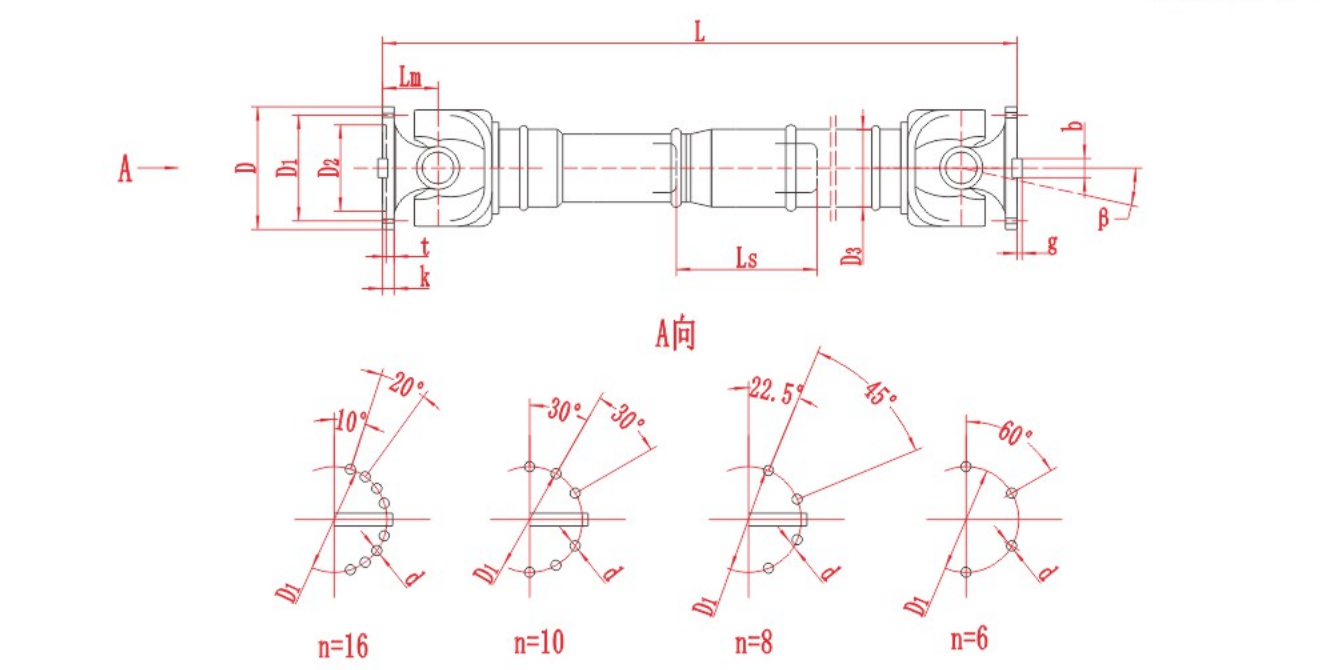
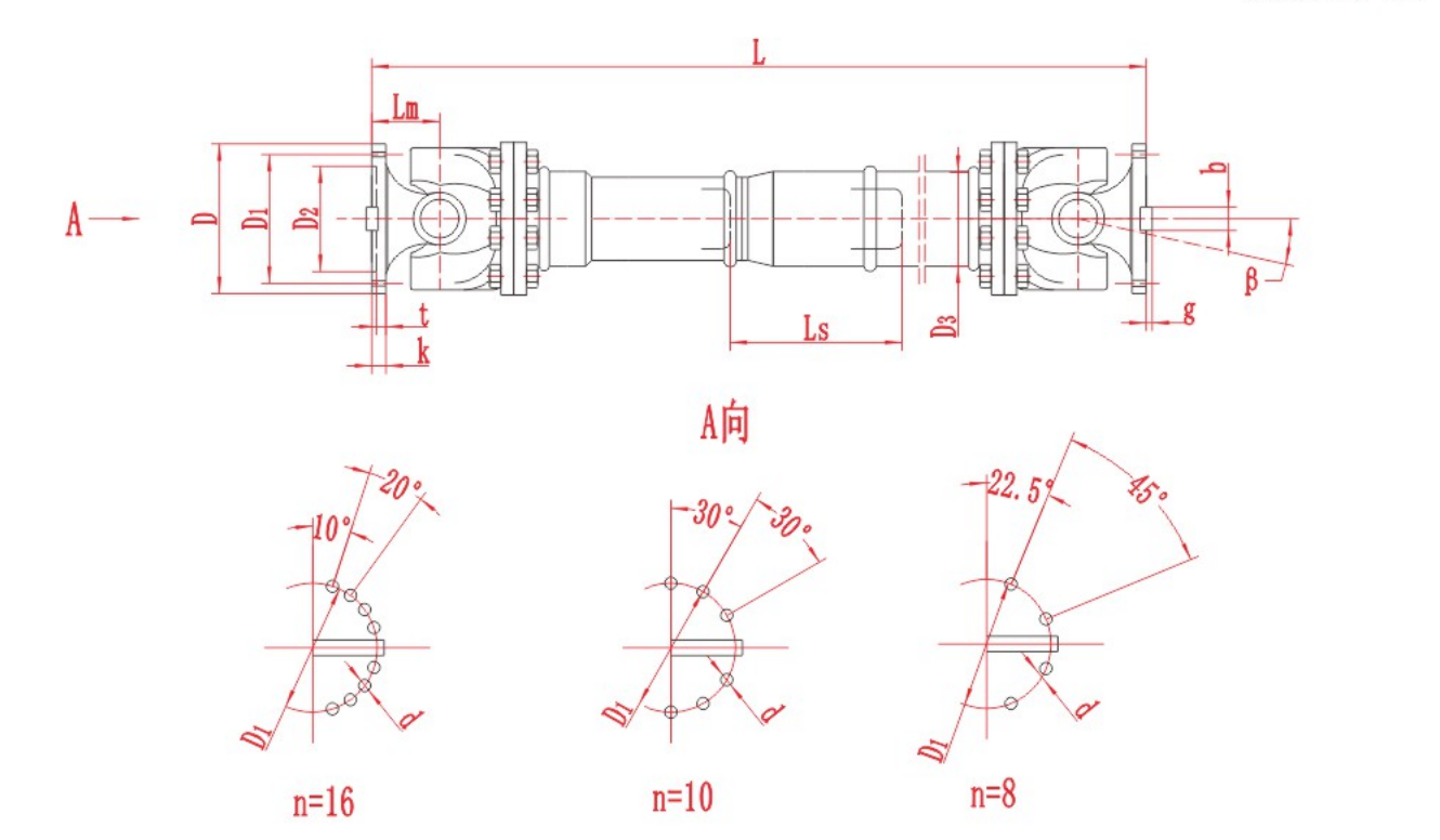
Figure 2. SWC-BH assembly drawing showing length, length compensation, operating angle and connection dimensions. Match each dimension symbol to the relevant product specification.
For a candidate such as the SWC-BH Telescopic Welded Cardan Shaft, check the required movement against the available length compensation and the permitted installed positions. Do not assume that all stated travel can be allocated in one direction from any starting position.
Where installation length is restricted, the SWC-DH Short Telescopic Welded Cardan Shaft provides another configuration to compare. Its suitability still depends on the load, movement and connection requirements.
A non-telescopic design, such as the SWC-WF Non-Telescopic Flanged Cardan Shaft, does not provide telescopic length compensation. Any required axial movement must therefore be addressed elsewhere in the system and confirmed during selection.
Check Flange Dimensions and Rotating Clearance
A similar-looking flange is not necessarily a compatible flange. Check the mating drawings, including:
Flange outside diameter.
Locating diameter and fit.
Bolt circle diameter.
Number and diameter of bolt holes.
Any keys, serrations or other torque-transmitting features.
Space for fasteners, tools and assembly.
Also check the envelope swept by the rotating joints. The swing diameter is not the same as the shaft tube diameter, and neither should be confused with the mating equipment’s shaft diameter.
The SWC-BF Telescopic Flanged Cardan Shaft can be considered when comparing structural arrangements. However, the terms “welded” and “flanged” do not, by themselves, establish whether an assembly has compatible end connections. Use the specific assembly drawing.
Allow for equipment movement and the proposed guarding arrangement when reviewing clearance. A shaft that fits while stationary may interfere with nearby components at another operating position.
Universal Joint Shaft Selection: Comparing SWC and SWP Designs
Once the load and installation requirements are defined, compare suitable shaft configurations rather than selecting solely by series name.
| RONGXING DRIVE configuration | Main selection question |
|---|---|
| SWC-BH Telescopic Welded Cardan Shaft | Does the assembly meet the load, length and movement requirements? |
| SWC-BF Telescopic Flanged Cardan Shaft | Does its structural arrangement suit the installation, with compatible connection dimensions? |
| SWC-DH Short Telescopic Welded Cardan Shaft | Can the shorter configuration meet the available length and required compensation? |
| SWC-WF Non-Telescopic Flanged Cardan Shaft | Is telescopic compensation unnecessary, and is the specified length suitable? |
| SWP-A Telescopic Long Cardan Shaft with Split Bearing Housing | Does this alternative construction meet the load, connection and installation requirements? |
The SWP-A design provides a split bearing housing construction and telescopic length compensation. It should be compared with SWC candidates using the actual specifications and drawings, not a general assumption that one series always carries more torque or lasts longer.
For every candidate, confirm the complete specification, including the required assembly length and connection details. A series designation alone is not a complete purchasing specification.
A Worked Example of Preliminary Cardan Shaft Sizing
The following example is hypothetical and demonstrates the checking process. It is not a recommendation for a particular RONGXING DRIVE model.
Assume an industrial drive has:
| Input | Assumed value |
|---|---|
| Mechanical power at the cardan shaft | 110 kW |
| Cardan shaft speed | 300 rpm |
| Normal connection distance | 1,200 mm |
| Connection distance during movement | 1,180 to 1,220 mm |
| Maximum working joint angle | 8° |
| Load behaviour | Repeated starts with occasional shock loading |
| Mating flange dimensions | Not yet supplied |
Step 1: Calculate Nominal Torque
T = 9550 × 110 ÷ 300 ≈ 3,502 N·m
The nominal torque is therefore approximately 3.50 kN·m.
This value does not include the additional effects of starting or shock loading.
Step 2: Establish the Movement Requirement
The connection distance varies by 40 mm between its minimum and maximum positions. This indicates a need to assess length compensation, but it does not prove that any shaft with 40 mm of stated travel is suitable.
The installed position, permitted extension, engagement and any additional assembly requirements still need confirmation.
Step 3: Review Candidate Configurations
A telescopic configuration such as SWC-BH or SWC-BF can be included in the initial comparison. Check its length range, compensation, torque parameters, angle and connection dimensions.
Step 4: Identify the Missing Information
The starting and shock torque, full shaft arrangement and mating flange dimensions remain unknown. These missing inputs prevent a final model from being confirmed.
The correct outcome is a preliminary shortlist and a technical enquiry, not an automatic model selection.
Prepare the Information for Technical Review
To discuss an SWC or SWP cardan shaft with RONGXING DRIVE, provide the operating data together with a dimensioned installation drawing.
Include the transmitted power or torque, shaft speed range, load behaviour, joint angles, connection distances, movement range and mating flange details. For replacement work, add photographs, identification markings and the reason for replacement.
If the existing shaft has experienced vibration, wear or damage, describe when the problem occurs. Selecting a replacement from dimensions alone may leave the original cause unresolved.
Final selection should confirm the load assessment, dimensional compatibility and relevant operating limits before manufacture or installation.
Frequently Asked Questions
What Dimensions Are Needed to Specify an Industrial Cardan Shaft?
Provide the installed length, minimum and maximum connection distances, flange dimensions and available rotating clearance. Identify the measurement reference planes so that the dimensions can be interpreted correctly.
Which Cardan Shaft Configurations Should Be Considered During Selection?
Compare telescopic and non-telescopic designs first, based on the movement requirement. Then assess structural variants, installation length and connection arrangements against the load and operating conditions.
Can a Cardan Shaft Be Selected from Motor Power Alone?
No. Power must be considered with the rotational speed at the cardan shaft. Selection also requires information about peak loads, repeated loading, joint angles, shaft length and connections.
What Is the Difference Between Rated Torque and Fatigue Torque?
They represent different load-related checks and are not interchangeable. Their application depends on the product’s rating definitions and the actual load cycle. Supply details of reversals, repeated loads and operating duty for technical review.
When Is a Telescopic Cardan Shaft Needed?
Telescopic compensation may be required when the distance between connected equipment changes or when the installation requires controlled length adjustment. The necessary travel and installed position must be checked against the specific design.
How Does Operating Angle Affect Universal Joint Shaft Selection?
Operating angle influences joint motion and must be considered with speed, load and shaft arrangement. A listed maximum angle does not establish suitability at every combination of these conditions.