Cardan Shafts
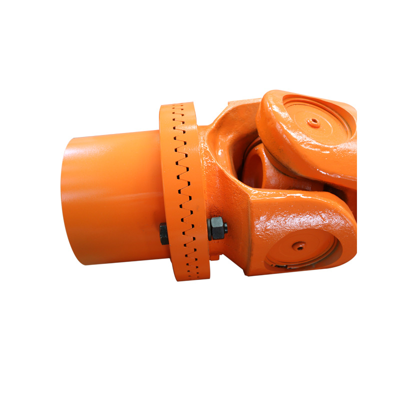
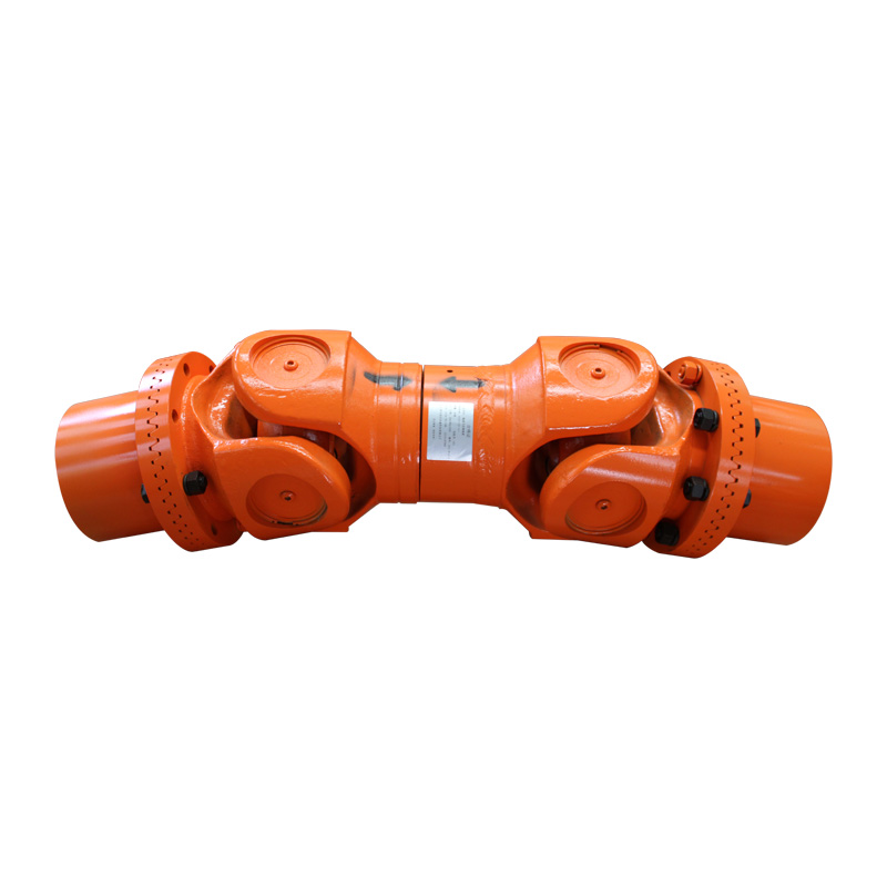
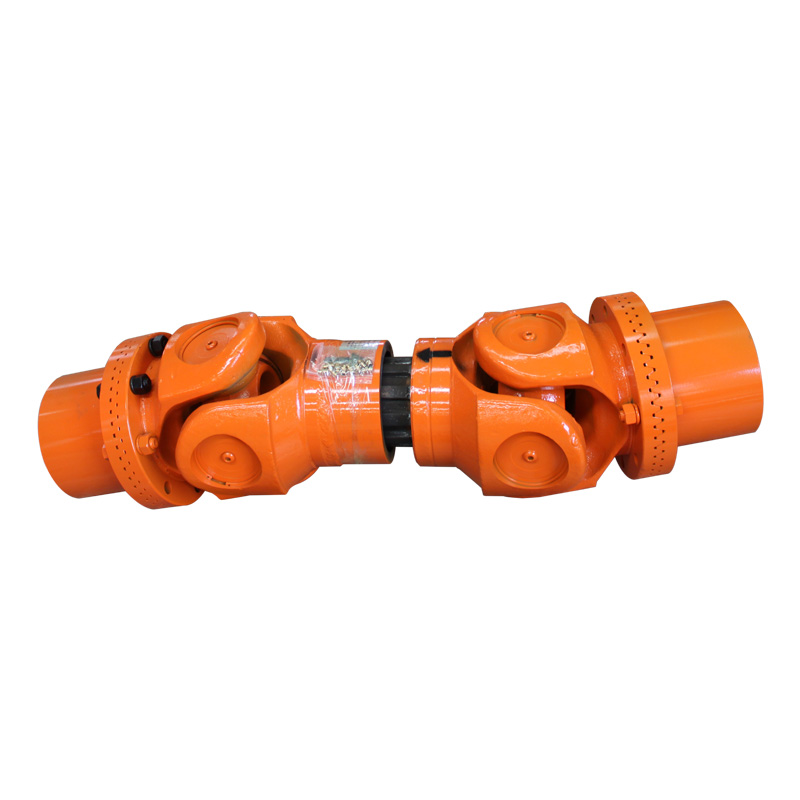
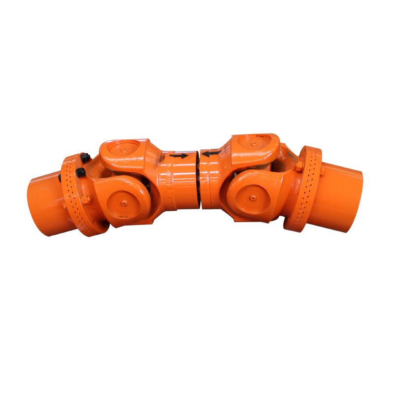
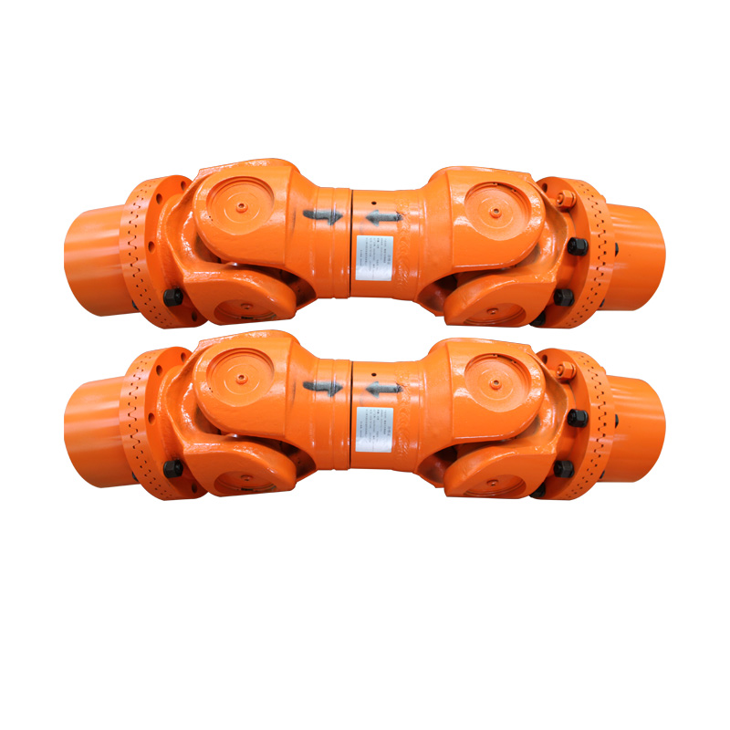
SWC-BH Telescopic Welded Cardan Shaft
SWC-BH telescopic welded cardan shaft with rated and fatigue torque, operating angle, length compensation, dimensions and assembly drawing.
Product Overview
The SWC-BH Telescopic Welded Cardan Shaft is a universal-joint shaft configuration for drive lines that require an operating angle and length compensation. The model table brings together swing diameter, rated torque, fatigue torque, operating angle, telescopic movement, minimum length, flange and shaft dimensions, inertia and mass. A complete inquiry should state the installed length and surrounding clearance as well as speed, torque, angle and flange interface, because the shaft geometry and duty are interdependent. The published data is intended for preliminary comparison; final phasing, connection dimensions, material, balancing and operating suitability require technical confirmation.
Key Features
- Telescopic welded cardan-shaft configuration
- Model data includes rated torque Tn and fatigue torque Tf
- Operating angle β and length compensation Ls are listed by model
- Drawing-based review of minimum length, flange dimensions, swing diameter, inertia and mass
Typical Selection Context
- Drive lines with an operating angle between connected shafts
- Equipment where relative movement requires length compensation
- Heavy-duty shaft-interface review using swing diameter and flange dimensions
Product Gallery
Technical Specification
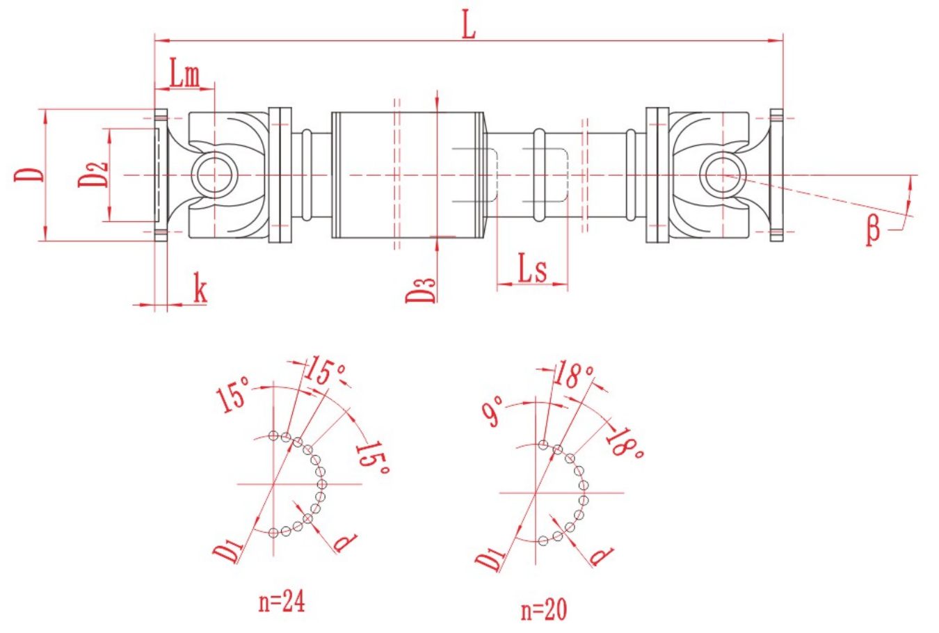
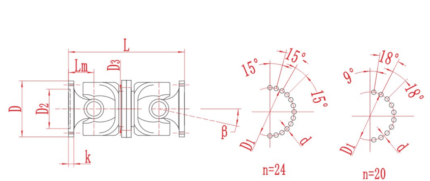
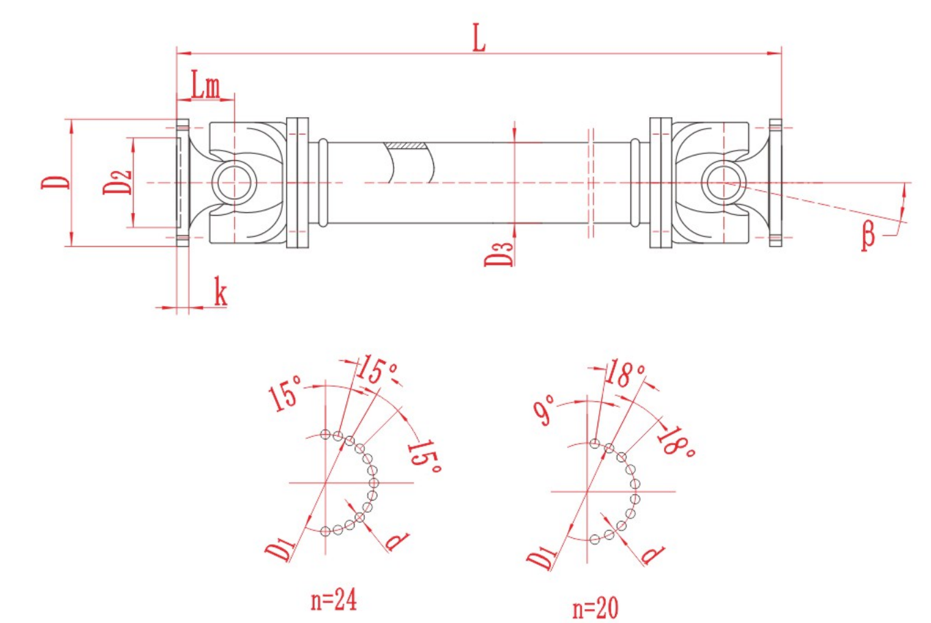
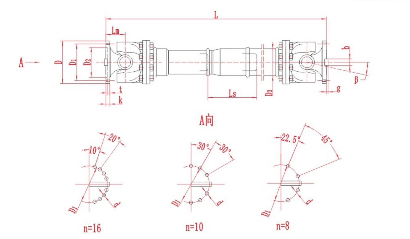
The following tables present the model and dimensional values available for preliminary comparison. Keep the relevant drawing with the selected row when reviewing a requirement.
| Model | Swing diameter D (mm) | Rated torque Tn (kN·m) | Fatigue torque Tf (kN·m) | Operating angle β (°) | Length compensation Lₛ(mm) | Dimensions (mm) Lₘᵢₙ | Dimensions (mm) D₁ (js11) | Dimensions (mm) D₂ (H7) | Dimensions (mm) D₃ | Dimensions (mm) Lₘ | Dimensions (mm) n-d | Dimensions (mm) k | Dimensions (mm) t | Dimensions (mm) b (h9) | Dimensions (mm) g | Mass moment of inertia (kg·m²) Lₘᵢₙ | Mass moment of inertia (kg·m²) per 100 mm increase | Mass (kg) Lₘᵢₙ | Mass (kg) per 100 mm increase |
|---|---|---|---|---|---|---|---|---|---|---|---|---|---|---|---|---|---|---|---|
| SWC100BH | 100 | 1.25 | 0.63 | ≤25 | 55 | 390 | 84 | 57 | 60 | 55 | 6-9 | 7 | 2.5 | - | - | 0.0044 | 0.00019 | 6.1 | 0.35 |
| SWC120BH | 120 | 2.5 | 1.25 | ≤25 | 80 | 485 | 102 | 75 | 70 | 65 | 8-11 | 8 | 2.5 | - | - | 0.0109 | 0.00044 | 10.8 | 0.55 |
| SWC150BH | 150 | 5 | 2.5 | ≤25 | 80 | 590 | 130 | 90 | 89 | 80 | 8-13 | 10 | 3.0 | - | - | 0.0423 | 0.00157 | 24.5 | 0.85 |
| SWC180BH | 180 | 12.5 | 6.3 | ≤25 | 100 | 810 | 155 | 105 | 114 | 110 | 8-17 | 17 | 5.0 | - | - | 0.1750 | 0.0070 | 70 | 2.8 |
| SWC225BH | 225 | 40 | 20 | ≤15 | 140 | 920 | 196 | 135 | 152 | 120 | 8-17 | 20 | 5.0 | 32 | 9.0 | 0.5380 | 0.0234 | 122 | 4.9 |
| SWC250BH | 250 | 63 | 31.5 | ≤15 | 140 | 1035 | 218 | 150 | 168 | 140 | 8-19 | 25 | 6.0 | 40 | 12.5 | 0.9660 | 0.0277 | 172 | 5.3 |
| SWC285BH | 285 | 90 | 45 | ≤15 | 140 | 1190 | 245 | 170 | 194 | 160 | 8-21 | 27 | 7.0 | 40 | 15.0 | 2.0110 | 0.0510 | 263 | 6.3 |
| SWC315BH | 315 | 125 | 63 | ≤15 | 140 | 1315 | 280 | 185 | 219 | 180 | 10-23 | 32 | 8.0 | 40 | 15.0 | 3.6050 | 0.0795 | 382 | 8.0 |
| SWC350BH | 350 | 180 | 90 | ≤15 | 150 | 1410 | 310 | 210 | 267 | 194 | 10-23 | 35 | 8.0 | 50 | 16.0 | 7.0530 | 0.2219 | 582 | 15.0 |
| SWC390BH | 390 | 250 | 125 | ≤15 | 170 | 1590 | 345 | 235 | 267 | 215 | 10-25 | 40 | 8.0 | 70 | 18.0 | 12.164 | 0.2219 | 738 | 15.0 |
| SWC440BH | 440 | 355 | 180 | ≤15 | 190 | 1875 | 390 | 255 | 325 | 260 | 16-28 | 42 | 10.0 | 80 | 20.0 | 21.420 | 0.4744 | 1190 | 21.7 |
| SWC490BH | 490 | 500 | 250 | ≤15 | 190 | 1985 | 435 | 275 | 325 | 270 | 16-31 | 47 | 12.0 | 90 | 22.5 | 32.860 | 0.4744 | 1452 | 21.7 |
| SWC550BH | 550 | 710 | 355 | ≤15 | 240 | 2300 | 492 | 320 | 426 | 305 | 16-31 | 50 | 12.0 | 100 | 22.5 | 68.920 | 1.3570 | 2380 | 34 |
Technical Notes
- Model symbols, units and empty or placeholder cells are shown as published.
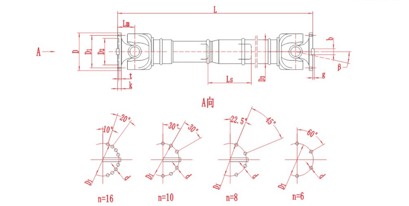
- Dimension letters must be interpreted with the relevant product drawing.
- Published values support preliminary review and do not replace final engineering confirmation.
Assembly Drawing
Referenced Standard
Referenced standard: JB 5513-91. Current applicability and equivalence should be confirmed before ordering.
Information Required for Selection
- Installed length L and required telescopic movement
- Operating angle β, swing-diameter clearance and surrounding envelope
- Nominal torque, peak torque, rated torque Tn and fatigue torque Tf
- Flange pilot, bolt-hole pattern, phasing and connection dimensions
- Normal and maximum speed, duty cycle and reversing or shock conditions
- Quantity, destination and inspection or documentation requirements
Product FAQ
What makes the SWC-BH telescopic?
The configuration includes length compensation and a minimum-length dimension for installation review.
What is fatigue torque Tf?
Tf is the fatigue torque value listed for alternating-load review.
Which dimensions are important for an inquiry?
State installed length, telescopic movement, operating angle, swing diameter, flange and bolt-hole dimensions, speed and torque.
Technical data is provided for preliminary selection. Confirm the final model, dimensions, materials, applicable standard and operating suitability with RONGXING DRIVE before quotation, manufacture or installation.