Gear Couplings
CLZ Gear Coupling
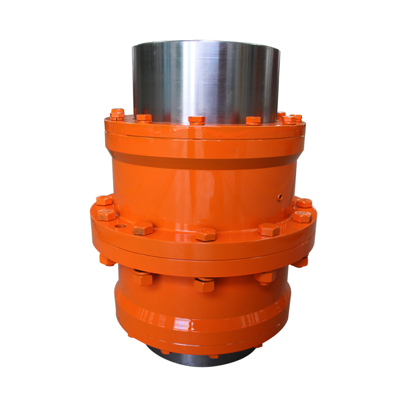
CLZ Gear Coupling with model-specific technical data, engineering context and assembly drawing for preliminary selection.
Product Overview
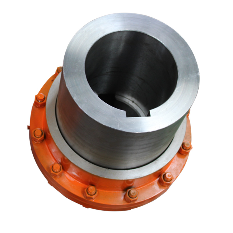
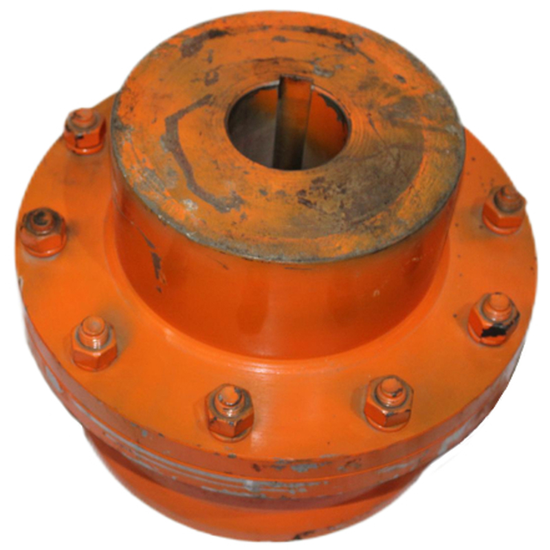
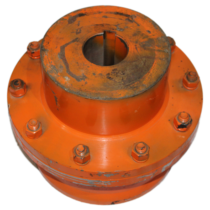
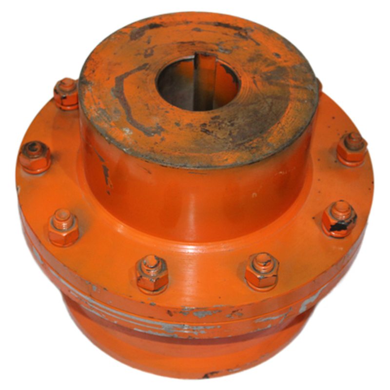
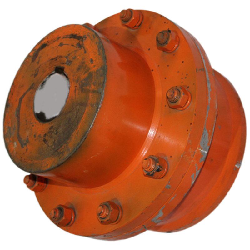
CLZ is the gear-coupling variant whose table emphasizes paired bore diameters, bore length, D-series dimensions, inertia and mass. The Z configuration should be selected from the exact drawing because its sleeve and bore geometry differ from CL. Gear teeth transmit the torque while the permissible displacement remains an alignment responsibility. The published model tables contain 19 size rows and provide torque values spanning 0.71–1000 N·m, permissible-speed values spanning 300–3780 r/min, bore values spanning 18–560 mm. Use those values for preliminary comparison only; final materials, current standards, manufacturing details and operating suitability require confirmation from RONGXING DRIVE.
Key Features
- CLZ-specific paired bore and D-series geometry
- Nominal torque, speed, inertia and mass by size
- Drawing-led review of tooth space and installation envelope
- The model data provides torque values spanning 0.71–1000 N·m, permissible-speed values spanning 300–3780 r/min, bore values spanning 18–560 mm for a traceable preliminary comparison.
Typical Selection Context
- Industrial drive lines using a CLZ gear-coupling layout
- Torque transmission where bore and sleeve dimensions are constrained
Product Gallery
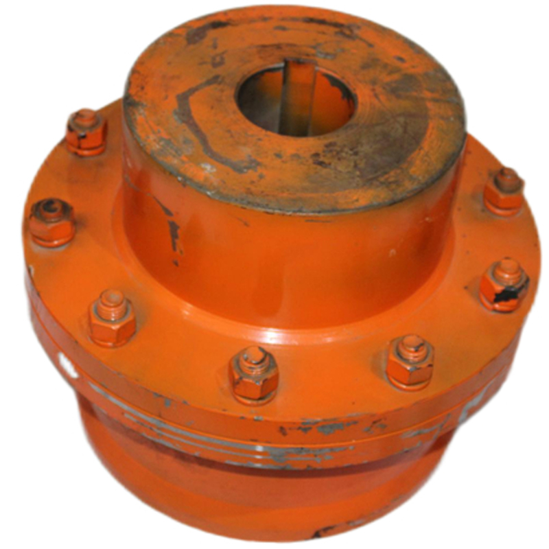
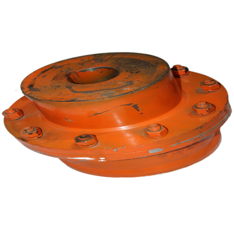
Technical Specification
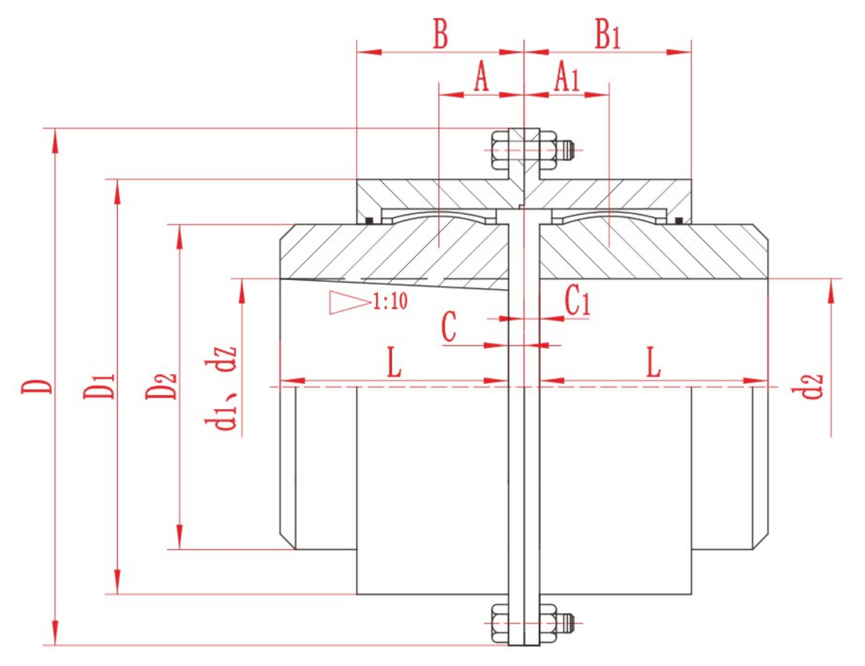
The following model tables are provided for preliminary comparison. Keep the relevant assembly drawing with the selected row.
| Model | Nominal torque Tn kN·m | Permissible speed [n] r/min | Bore diameter d₁ dz | Bore length L Y | D | D₁ | D₂ | D₃ | C | Mass moment of inertia kg·m² | Mass kg |
|---|---|---|---|---|---|---|---|---|---|---|---|
| CLZ1 | 0.71 | 3780 | 18~40 (60) | 40~142 | 170 | 110 | 55 | 95 | 2.5 | 0.03 | 11.8 |
| CLZ2 | 1.4 | 3000 | 30~50 (70) | 82~142 | 185 | 125 | 70 | 110 | 2.5 | 0.06 | 16.6 |
| CLZ3 | 3.15 | 2400 | 40~60 (90) | 112~172 | 220 | 150 | 90 | 145 | 2.5 | 0.12 | 34.8 |
| CLZ4 | 5.6 | 2000 | 45~75 (100) | 112~212 | 250 | 175 | 110 | 170 | 2.5 | 0.22 | 47.8 |
| CLZ5 | 8 | 1680 | 50~90 (120) | 112~212 | 290 | 200 | 130 | 190 | 5 | 0.44 | 67.3 |
| CLZ6 | 11.2 | 1500 | 60~110 (130) | 142~252 | 320 | 230 | 140 | 210 | 5 | 0.75 | 91 |
| CLZ7 | 18 | 1270 | 65~120 (150) | 142~252 | 350 | 260 | 170 | 240 | 5 | 1.25 | 125 |
| CLZ8 | 23.6 | 1140 | 80~140 (170) | 172~302 | 380 | 315 | 190 | 270 | 5 | 2.06 | 174 |
| CLZ9 | 28 | 1000 | 90~160 (190) | 172~352 | 430 | 365 | 210 | 280 | 5 | 2.56 | 210 |
| CLZ10 | 50 | 850 | 110~180 (220) | 212~352 | 490 | 420 | 260 | 320 | 5 | 5 | 298 |
| CLZ11 | 71 | 750 | 120~220 (250) | 212~410 | 545 | 470 | 300 | 380 | 5 | 9.25 | 447 |
| CLZ12 | 100 | 660 | 140~250 (280) | 252~470 | 590 | 520 | 340 | 420 | 5 | 12.5 | 630 |
| CLZ13 | 140 | 600 | 160~280 (300) | 302~470 | 680 | 590 | 380 | 480 | 7.5 | 29.9 | 897 |
| CLZ14 | 200 | 540 | 180~320 (340) | 302~550 | 730 | 650 | 420 | 520 | 7.5 | 42.5 | 1118 |
| CLZ15 | 250 | 480 | 200~360 (380) | 352~550 | 780 | 700 | 480 | 560 | 7.5 | 56.9 | 1495 |
| CLZ16 | 355 | 425 | 240~360 (420) | 410~650 | 900 | 785 | 530 | 650 | 10 | 120 | 2008 |
| CLZ17 | 560 | 380 | 260~450 (480) | 410~650 | 1000 | 885 | 630 | 750 | 10 | 252 | 3021 |
| CLZ18 | 710 | 330 | 300~530 | 470~800 | 1100 | 990 | 710 | 820 | 10 | 325 | 4004 |
| CLZ19 | 1000 | 300 | 360~560 | 550~800 | 1250 | 1090 | 800 | 920 | 15 | 568 | 5458 |
Engineering Context
This model is best understood from its own construction: CLZ-specific paired bore and D-series geometry; Nominal torque, speed, inertia and mass by size; Drawing-led review of tooth space and installation envelope Industry selection practice checks torque and speed together with the movement, shaft interface, installation envelope and maintenance conditions allowed by that construction.
Technical Notes
- Model symbols, units and empty or placeholder cells are shown as published.
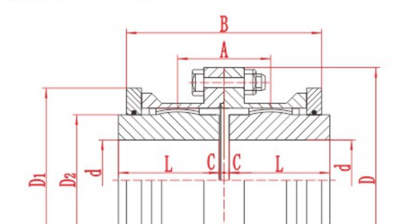
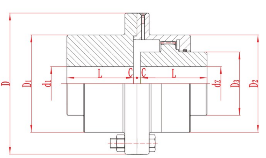
- Dimension letters must be interpreted with the relevant assembly drawing.
- Published values support preliminary review and do not replace final engineering confirmation.
Assembly Drawing
Information Required for Selection
- Compare CLZ bore pair, length, D dimensions and keyways
- Confirm lubrication, displacement, speed, inertia and guarding
- Send the exact model row, assembly drawing and actual duty data with the inquiry.
Product FAQ
Should CLZ be interchanged with CL?
No. Treat the model families as distinct and verify the exact bore and drawing.
How is displacement handled?
Use the specified tooth geometry and alignment limits; do not infer capacity from bore size.
Are the published values final ordering values?
No. They are preliminary engineering data; confirm the selected model, drawing, dimensions, materials, standard and suitability with RONGXING DRIVE.
Technical data is provided for preliminary selection. Confirm the final model, dimensions, materials, applicable standard and operating suitability with RONGXING DRIVE before quotation, manufacture or installation.