
Gear Couplings
GSL-F Telescopic Crowned Gear Coupling, Reverse Mounting
GSL-F Telescopic Crowned Gear Coupling, Reverse Mounting with model-specific technical data, engineering context and assembly drawing for preliminary selection.
Product Overview
GSL-F is the reverse-mounted telescopic GSL universal-joint configuration. Its model table is organized around nominal torque, operating angle, several overall lengths, minimum length, trunnion dimensions and length compensation. The reverse mounting orientation is an interface requirement, not a cosmetic option, so the drawing must accompany the inquiry. The published model tables contain 34 size rows and provide torque values spanning 31.5–1600 N·m, operating-angle values spanning 1.5 °. Use those values for preliminary comparison only; final materials, current standards, manufacturing details and operating suitability require confirmation from RONGXING DRIVE.
Key Features
- Reverse-mounted telescopic universal-joint arrangement
- Operating angle and length compensation by model
- Trunnion and multi-length dimensions for installation planning
- The model data provides torque values spanning 31.5–1600 N·m, operating-angle values spanning 1.5 ° for a traceable preliminary comparison.
Typical Selection Context
- Angled heavy-equipment drives with reverse mounting space
- Rolling or process machinery requiring telescopic travel and a defined trunnion interface
Technical Specification
The following model tables are provided for preliminary comparison. Keep the relevant assembly drawing with the selected row.
| Model | Nominal torque Tn kN·m | Operating angle β | Overall dimensions L₁ | Overall dimensions L₂ | Overall dimensions L₃ | Overall dimensions L₄ | Overall dimensions L₅ | Overall dimensions Lmin | Overall dimensions D₁ | Overall dimensions D₂ (h8) | Overall dimensions D₃ | Overall dimensions D₄ | Overall dimensions D₅ | Overall dimensions D₆ | Length compensation S | Trunnion dimensions d₁ (f8) | Trunnion dimensions l₁ | Trunnion dimensions l₂ | Trunnion dimensions d₂×H1 |
|---|---|---|---|---|---|---|---|---|---|---|---|---|---|---|---|---|---|---|---|
| GSL-F200 | 31.5 | ≤1.5° | 90 | 250 | 50 | 80 | 190 | 960 | 200 | 200 | 170 | 88 | 200 | 90 | 500 | 40 | 200 | 345 | M20×35 |
| GSL-F250 | 50 | 105 | 280 | 60 | 90 | 195 | 1050 | 250 | 258 | 220 | 105 | 250 | 107 | 45 | 270 | 425 | M20×35 | ||
| GSL-F285 | 80 | 115 | 315 | 60 | 105 | 205 | 1140 | 285 | 270 | 245 | 120 | 270 | 122 | 50 | 278 | 442 | M20×40 | ||
| GSL-F300 | 100 | 115 | 315 | 62 | 108 | 205 | 1165 | 300 | 280 | 250 | 124 | 280 | 126 | 600 | 50 | 292 | 487 | M24×45 | |
| GSL-F335 | 140 | 130 | 360 | 65 | 135 | 235 | 1315 | 335 | 330 | 280 | 150 | 300 | 152 | 55 | 293 | 488 | M24×45 | ||
| GSL-F355 | 180 | 130 | 360 | 75 | 145 | 245 | 1360 | 355 | 350 | 310 | 174 | 330 | 176 | 55 | 312 | 505 | M24×45 | ||
| GSL-F390 | 224 | 140 | 390 | 80 | 155 | 255 | 1450 | 390 | 380 | 335 | 180 | 360 | 182 | 60 | 360 | 570 | M24×50 | ||
| GSL-F405 | 250 | 140 | 390 | 80 | 155 | 255 | 1450 | 405 | 400 | 340 | 194 | 390 | 196 | 60 | 390 | 580 | M24×50 | ||
| GSL-F440 | 315 | 150 | 430 | 85 | 165 | 260 | 1540 | 440 | 440 | 375 | 208 | 410 | 210 | 65 | 420 | 650 | M24×50 | ||
| GSL-F475 | 400 | 155 | 460 | 85 | 165 | 265 | 1600 | 475 | 480 | 415 | 220 | 450 | 222 | 70 | 460 | 684 | M36×70 | ||
| GSL-F510 | 500 | 160 | 490 | 90 | 180 | 310 | 1750 | 510 | 520 | 430 | 245 | 480 | 247 | 700 | 80 | 500 | 770 | M36×70 | |
| GSL-F550 | 630 | 160 | 510 | 95 | 180 | 310 | 1770 | 550 | 550 | 470 | 252 | 510 | 254 | 85 | 520 | 800 | M36×70 | ||
| GSL-F580 | 750 | 165 | 515 | 98 | 185 | 320 | 1790 | 580 | 560 | 485 | 258 | 525 | 260 | 90 | 540 | 850 | M42×80 | ||
| GSL-F610 | 840 | 225 | 580 | 105 | 210 | 360 | 2060 | 610 | 610 | 520 | 280 | 580 | 282 | 100 | 600 | 940 | M42×80 | ||
| GSL-F660 | 1050 | 245 | 640 | 115 | 230 | 390 | 2230 | 660 | 660 | 540 | 295 | 630 | 297 | 100 | 650 | 990 | M42×80 | ||
| GSL-F710 | 1300 | 265 | 680 | 125 | 250 | 410 | 2380 | 710 | 710 | 580 | 315 | 680 | 317 | 110 | 700 | 1070 | M42×80 | ||
| GSL-F760 | 1600 | 290 | 730 | 135 | 260 | 430 | 2540 | 760 | 760 | 620 | 340 | 740 | 342 | 120 | 750 | 1150 | M42×80 |
| Model | Roll-end connection dimensions d₃ₘₐₓ nominal dimension | limit deviation | Roll-end connection dimensions H₂ₘₐₓ nominal dimension | limit deviation | l₃ₘₐₓ | l₄ₘₐₓ | C | Gearbox-end connection dimensions d₄ (H8) | d₅ (H7) | d₆ (JS10) | m×z | n×d₇×H₃ | l₅ | l₆ | l₇ | Mass kg Lₘᵢₙ | per 100 mm increase | Mass moment of inertia kg·m² Lₘᵢₙ | per 100 mm increase |
|---|---|---|---|---|---|---|---|---|---|---|---|---|---|---|---|---|---|---|---|
| GSL-F200 | 125 | 95 | 135 | 175 | 10 | 155 | 130 | 110 | 4×36 | 6×M10×25 | 35 | 85 | 120 | 162 | 4.77 | 0.81 | 0.02 | ||
| GSL-F250 | 150 | +0.20 +0.10 | 110 | +0.20 +0.10 | 195 | 235 | 15 | 195 | 170 | 150 | 4×46 | 8×M10×25 | 35 | 90 | 125 | 226 | 6.80 | 1.77 | 0.05 |
| GSL-F285 | 165 | 120 | 205 | 245 | 220 | 195 | 175 | 4×46 | 10×M10×25 | 40 | 95 | 130 | 317 | 8.88 | 3.22 | 0.09 | |||
| GSL-F300 | 180 | 130 | 210 | 250 | 220 | 195 | 175 | 5×42 | 12×M12×30 | 45 | 100 | 132 | 352 | 9.48 | 3.96 | 0.11 | |||
| GSL-F335 | 195 | +0.25 +0.15 | 150 | +0.25 +0.15 | 210 | 255 | 245 | 220 | 200 | 5×46 | 12×M12×30 | 50 | 100 | 150 | 508 | 13.87 | 7.13 | 0.19 | |
| GSL-F355 | 195 | 150 | 215 | 255 | 260 | 240 | 220 | 5×50 | 12×M12×30 | 50 | 100 | 150 | 574 | 18.67 | 9.04 | 0.29 | |||
| GSL-F390 | 220 | +0.35 +0.20 | 170 | +0.35 +0.20 | 230 | 275 | 25 | 280 | 260 | 240 | 5×54 | 12×M12×30 | 50 | 100 | 150 | 727 | 19.98 | 13.82 | 0.38 |
| GSL-F405 | 240 | 180 | 240 | 285 | 305 | 280 | 260 | 5×58 | 12×M12×30 | 50 | 110 | 155 | 874 | 23.20 | 17.92 | 0.48 | |||
| GSL-F440 | 260 | 190 | 250 | 295 | 336 | 306 | 276 | 6×54 | 12×M16×40 | 50 | 115 | 155 | 944 | 26.67 | 22.84 | 0.65 | |||
| GSL-F475 | 280 | 210 | 272 | 317 | 365 | 330 | 300 | 6×58 | 12×M16×40 | 50 | 115 | 155 | 1159 | 29.84 | 32.69 | 0.84 | |||
| GSL-F510 | 300 | +0.40 +0.25 | 230 | +0.40 +0.25 | 300 | 355 | 30 | 390 | 345 | 315 | 6×62 | 12×M16×40 | 50 | 130 | 170 | 1707 | 37.01 | 55.50 | 1.20 |
| GSL-F550 | 320 | 240 | 320 | 375 | 400 | 370 | 320 | 6×64 | 12×M16×40 | 50 | 130 | 170 | 1723 | 39.15 | 65.15 | 1.48 | |||
| GSL-F580 | 340 | 260 | 325 | 388 | 405 | 370 | 320 | 6×66 | 12×M16×40 | 50 | 135 | 175 | 1966 | 41.04 | 82.67 | 1.73 | |||
| GSL-F610 | 400 | 300 | 420 | 470 | 35 | 455 | 420 | 370 | 8×54 | 12×M20×50 | 50 | 160 | 210 | 2741 | 48.34 | 127.49 | 2.25 | ||
| GSL-F660 | 420 | 320 | 440 | 500 | 485 | 440 | 400 | 8×58 | 12×M20×50 | 60 | 180 | 230 | 3470 | 53.65 | 188.94 | 2.92 | |||
| GSL-F710 | 460 | 350 | 480 | 540 | 40 | 530 | 475 | 430 | 10×50 | 12×M20×50 | 60 | 190 | 240 | 4051 | 61.18 | 255.26 | 3.85 | ||
| GSL-F760 | 500 | 380 | 530 | 590 | 570 | 515 | 470 | 10×54 | 12×M20×50 | 60 | 200 | 250 | 5037 | 71.27 | 363.67 | 5.15 |
Engineering Context
This model is best understood from its own construction: Reverse-mounted telescopic universal-joint arrangement; Operating angle and length compensation by model; Trunnion and multi-length dimensions for installation planning Industry selection practice checks torque and speed together with the movement, shaft interface, installation envelope and maintenance conditions allowed by that construction.
Technical Notes
Model symbols, units and empty or placeholder cells are shown as published.
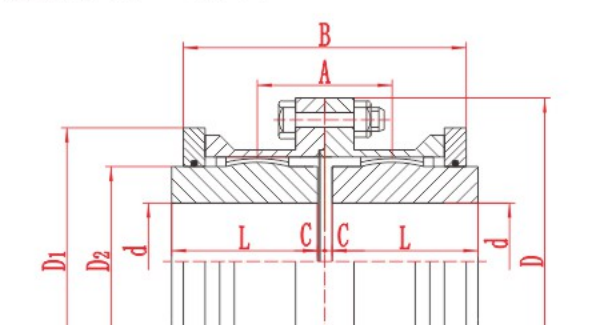
Dimension letters must be interpreted with the relevant assembly drawing.
Published values support preliminary review and do not replace final engineering confirmation.
Assembly Drawing
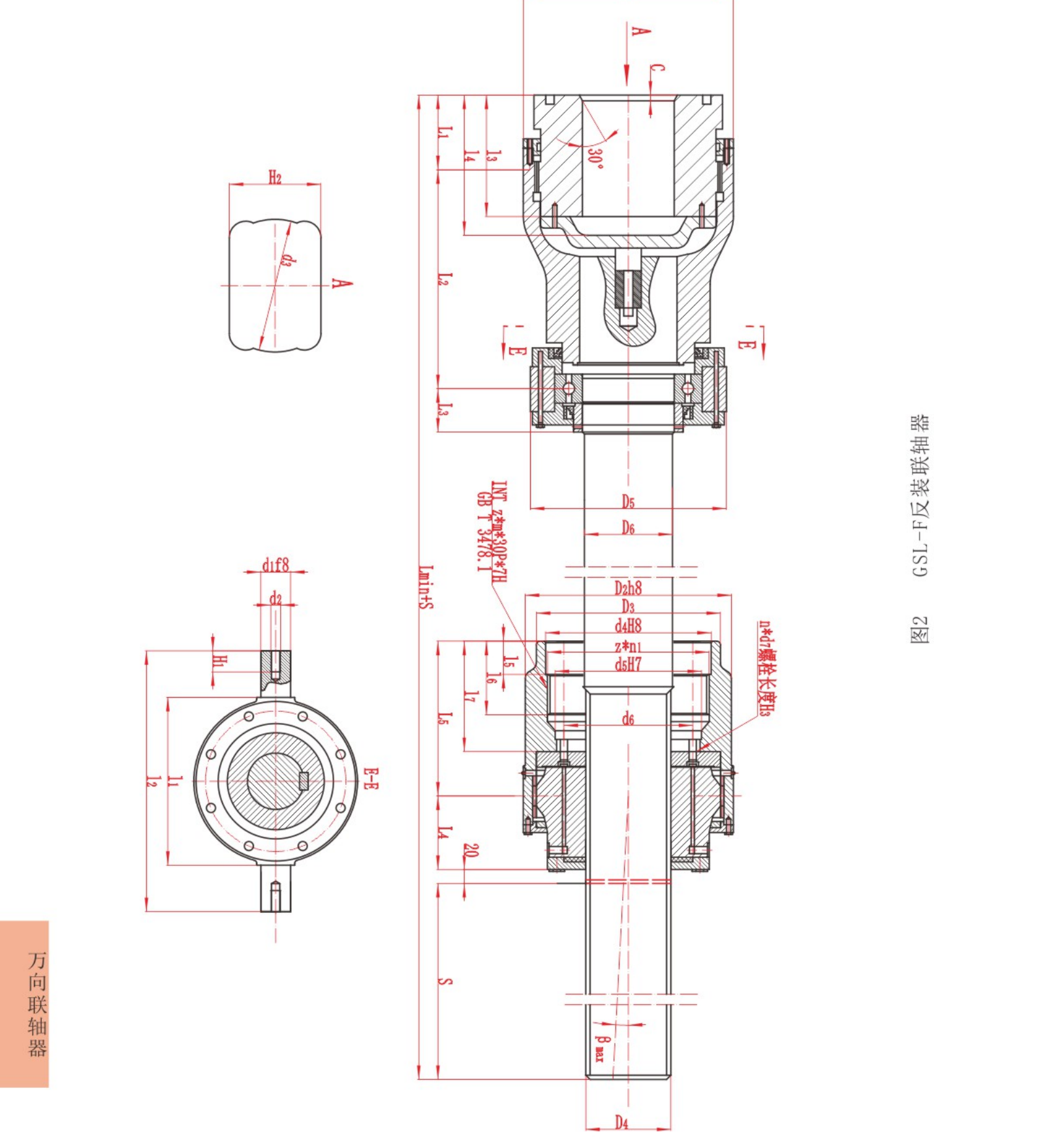
Information Required for Selection
- State mounting orientation, span, angle and required compensation
- Check trunnion dimensions, minimum length, torque and swing clearance
- Send the exact model row, assembly drawing and actual duty data with the inquiry.
Product FAQ
What does reverse mounting change?
It changes the connection orientation and available installation space; confirm the complete drawing orientation.
Why are several overall lengths listed?
The GSL-F envelope depends on the selected angle and mounting geometry.
Are the published values final ordering values?
No. They are preliminary engineering data; confirm the selected model, drawing, dimensions, materials, standard and suitability with RONGXING DRIVE.
Technical data is provided for preliminary selection. Confirm the final model, dimensions, materials, applicable standard and operating suitability with RONGXING DRIVE before quotation, manufacture or installation.
Leave a Comment
Questions and practical feedback are welcome. Comments are reviewed before publication.