Rigid & Special Couplings
GL Roller Chain Coupling
GL roller chain coupling with 40–25000 N·m nominal torque data, covered and uncovered speed values, dimensions and assembly drawing.
Product Overview
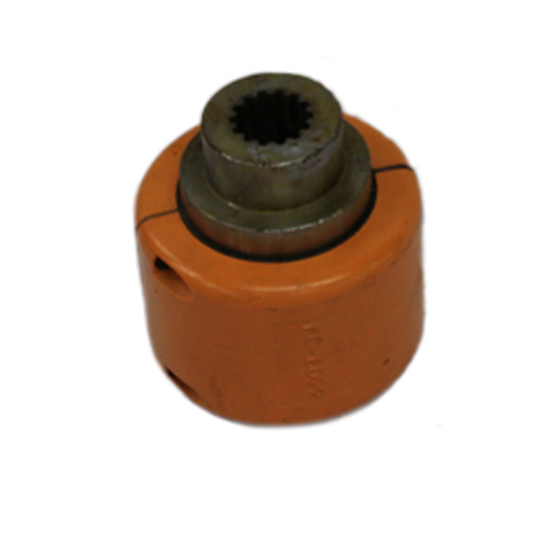
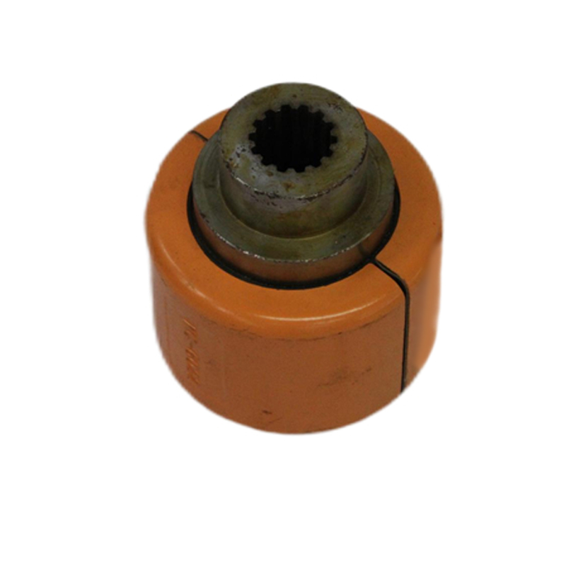
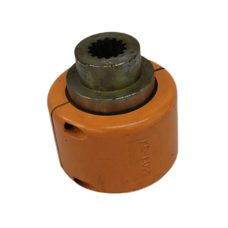
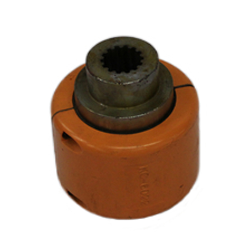
The GL Roller Chain Coupling is a chain-type coupling for coaxial drive systems. Its technical presentation provides model-specific nominal torque, permissible speed with and without a cover, bore range, bore length, chain number, principal dimensions and mass. Preliminary selection should consider the shaft connection at both ends together with alignment, lubrication, guarding and dismantling space. The listed GL models cover nominal torque from 40 to 25000 N·m. Covered and uncovered speed values are shown separately, and the mass and inertia basis should be retained when comparing installation loads. Confirm the final model and guarding arrangement before ordering.
Key Features
- Roller-chain coupling structure for coaxial drive systems
- Separate permissible-speed values with and without a cover
- Model table includes bore, bore length, chain number and principal dimensions
- Selection review includes lubrication, guarding, alignment and dismantling space
Typical Selection Context
- Coaxial drive systems using a roller-chain coupling arrangement
- Installations where guarding and maintenance access must be planned
- Torque transmission duties within the published GL model range
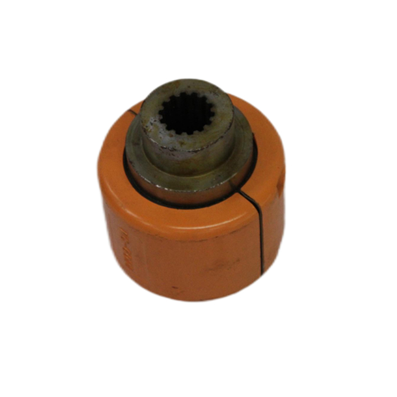
Product Gallery
Technical Specification
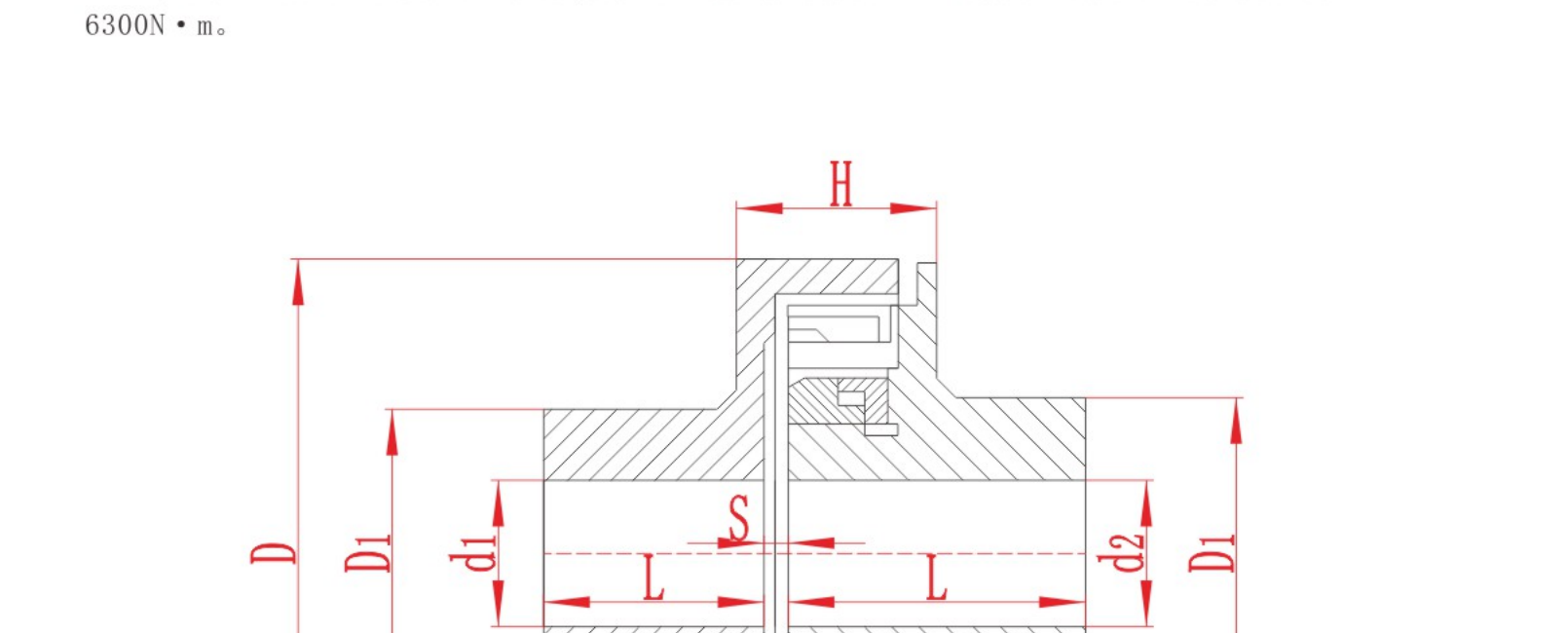
The following tables present the model and dimensional values available for preliminary comparison. Keep the relevant drawing with the selected row when reviewing a requirement.
| Model | Nominal torque Tn N·m | Permissible speed [n] r/min without cover | Permissible speed [n] r/min with cover | Bore diameter d | Bore length Y type J₁ type L | Chain number | Dimensions D | Dimensions bn | Dimensions S | Dimensions D₁ | Dimensions Cover Dk×Lk max | Mass kg |
|---|---|---|---|---|---|---|---|---|---|---|---|---|
| GL1 | 40 | 1400 | 4500 | 16~20 | 38~52 | TG95×2 | 51.06 | 5.3 | 4.9 | 32 | 70×70 | 0.5 |
| GL2 | 63 | 1250 | 4500 | 19~24 | 38~52 | TG95×2 | 57.08 | 5.3 | 4.9 | 38 | 75×75 | 0.8 |
| GL3 | 100 | 1000 | 4000 | 20~25 | 38~63 | TG127×2 | 68.88 | 7.2 | 6.7 | 40 | 85×80 | 1.2 |
| GL4 | 160 | 1000 | 4000 | 24~32 | 44~82 | TG127×2 | 79.61 | 7.2 | 6.7 | 50 | 95×88 | 2 |
| GL5 | 250 | 800 | 3150 | 28~40 | 60~112 | TG158×2 | 94.46 | 8.9 | 9.2 | 60 | 112×100 | 3.5 |
| GL6 | 400 | 630 | 2500 | 32~50 | 60~112 | TG158×2 | 116.57 | 8.9 | 9.2 | 80 | 140×105 | 5 |
| GL7 | 630 | 630 | 2500 | 40~60 | 84~142 | TG190×2 | 127.78 | 11.9 | 10.9 | 85 | 150×122 | 8 |
| GL8 | 1000 | 500 | 2240 | 45~70 | 84~142 | TG254×2 | 154.33 | 15 | 14.3 | 100 | 180×135 | 12 |
| GL9 | 1600 | 400 | 2000 | 50~80 | 84~172 | TG254×2 | 186.5 | 15 | 14.3 | 132 | 215×145 | 20 |
| GL10 | 2500 | 315 | 1600 | 65~90 | 107~172 | TG137×2 | 213.02 | 18 | 17.8 | 145 | 245×165 | 27 |
| GL11 | 4000 | 250 | 1500 | 75~100 | 107~212 | TG381×2 | 231.49 | 24 | 21.5 | 155 | 270×195 | 40 |
| GL12 | 6300 | 250 | 1250 | 85~120 | 132~212 | TG444×2 | 270.08 | 24 | 24.9 | 180 | 310×205 | 60 |
| GL13 | 10000 | 200 | 1120 | 100~140 | 167~252 | TG508×2 | 340.8 | 30 | 28.6 | 230 | 380×230 | 88 |
| GL14 | 16000 | 200 | 1000 | 120~160 | 167~302 | TG508×2 | 405.22 | 30 | 28.6 | 280 | 450×250 | 152 |
| GL15 | 25000 | 200 | 900 | 140~190 | 202~352 | TG635×2 | 466.25 | 36 | 35.6 | 320 | 510×285 | 235 |
Technical Notes
- Model symbols, units and empty or placeholder cells are shown as published.
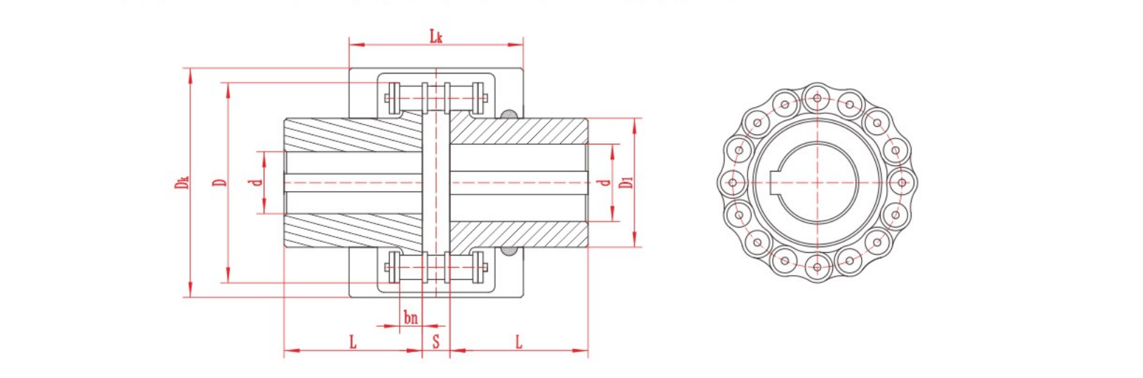
- Dimension letters must be interpreted with the relevant product drawing.
- Published values support preliminary review and do not replace final engineering confirmation.
Assembly Drawing
Referenced Standard
Referenced standard: GB/T 6069-2002. Current applicability and equivalence should be confirmed before ordering.
Information Required for Selection
- Nominal, starting and peak torque; normal and maximum speed
- Shaft diameters, bore lengths and keyway configuration
- Speed requirement with or without a cover
- Alignment, lubrication, guarding and dismantling clearance
- Ambient temperature, dust, corrosion and maintenance conditions
- Required quantity, destination and inspection or documentation requirements
Product FAQ
What speed information is listed for GL?
The table provides separate permissible-speed values for configurations without a cover and with a cover.
What is the GL torque range?
The listed model data covers nominal torque from 40 to 25000 N·m.
Does the listed mass include the cover?
The cover and coupling body are treated separately in the technical notes; confirm the exact mass basis for the selected configuration before installation.
Technical data is provided for preliminary selection. Confirm the final model, dimensions, materials, applicable standard and operating suitability with RONGXING DRIVE before quotation, manufacture or installation.