Technical Resources
Shaft Flange Coupling Types, Parts and Applications
A shaft flange coupling transmits torque between two rotating shafts through flanges bolted together at their faces. In a rigid design, each flange is attached to its shaft and the bolted joint holds the two halves together. The machine must keep the
A shaft flange coupling transmits torque between two rotating shafts through flanges bolted together at their faces. In a rigid design, each flange is attached to its shaft and the bolted joint holds the two halves together. The machine must keep the shafts within the specified alignment limits. Flexible assemblies can also have flanges, with movement accommodated by a separate element such as a pin and bush.
Parts of a flange coupling
| Part | What it does | What to verify |
|---|---|---|
| Hubs and bores | Locate the coupling halves on the shafts. | Both bore sizes, fit, engagement length and shaft-end positions. |
| Keys or other shaft attachment | Connect each hub to its shaft according to the design. | Keyway size and location or the specified alternative attachment. |
| Flanges and fasteners | Join the coupling halves and transmit load through the designed joint. | Bolt circle, hole count and diameter, flange faces and approved fasteners. |
| Pilot or centring register, where fitted | Locates the two halves radially during assembly. | Register diameter, depth and fit on the mating drawing. |
Types of flange coupling
Traditional machine design texts distinguish unprotected, protected and marine-type rigid flange couplings. The terms describe how the joint is built and how the fasteners are arranged. Rohini College of Engineering and Technology’s flange coupling notes illustrate the three layouts.
Unprotected. The bolt heads and nuts project beyond the flange faces. Allow space for the fasteners and the tools needed to reach them.
Protected. A rim on the flange surrounds the projecting fasteners. Check the equipment’s guarding requirements separately.
Marine type. In the traditional textbook design, the flanges are integral with the shafts. Use the shaft and joint drawings when assessing a replacement.
For industrial procurement, also check whether the torque-transmitting assembly is rigid or flexible. A flexible pin bush coupling uses pins and resilient bushes between flanged halves. Pipe flanges form a sealed connection between pipes and are outside the scope of this shaft coupling guide. Compare rigid and flexible shaft couplings.
Flange coupling applications and uses
A rigid flange coupling is a candidate for a machine train designed around a fixed connection between coaxial shafts. Examples include sections of a line shaft or a gearbox-to-machine connection specified with a rigid joint. Check whether the supports maintain alignment under load and during warm-up. For a pump or other machine that needs movement accommodation or extra service clearance, check the equipment specification for the required coupling arrangement.
How to check a GY replacement
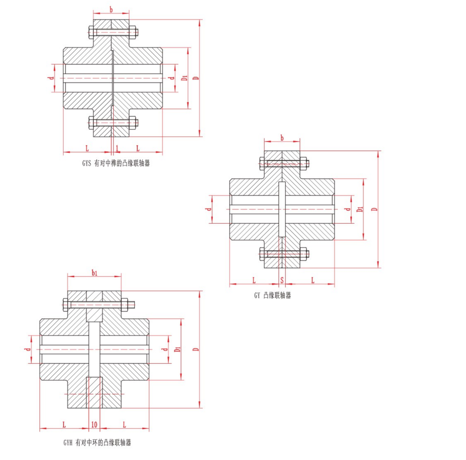
Use the RONGXING DRIVE GY Flange Coupling drawing as the starting point. Compare both shafts, the flange outside diameter, the bolt pattern, any centring register and the available axial space. A matching bolt circle alone cannot confirm fit. For an Indian industrial replacement, provide the existing drawing, the shaft dimensions at both ends, operating speed, torque and any project requirements. Confirm the replacement against the approved assembly drawing before machining or installation.