Gear Couplings
GICLZ Crowned Gear Coupling
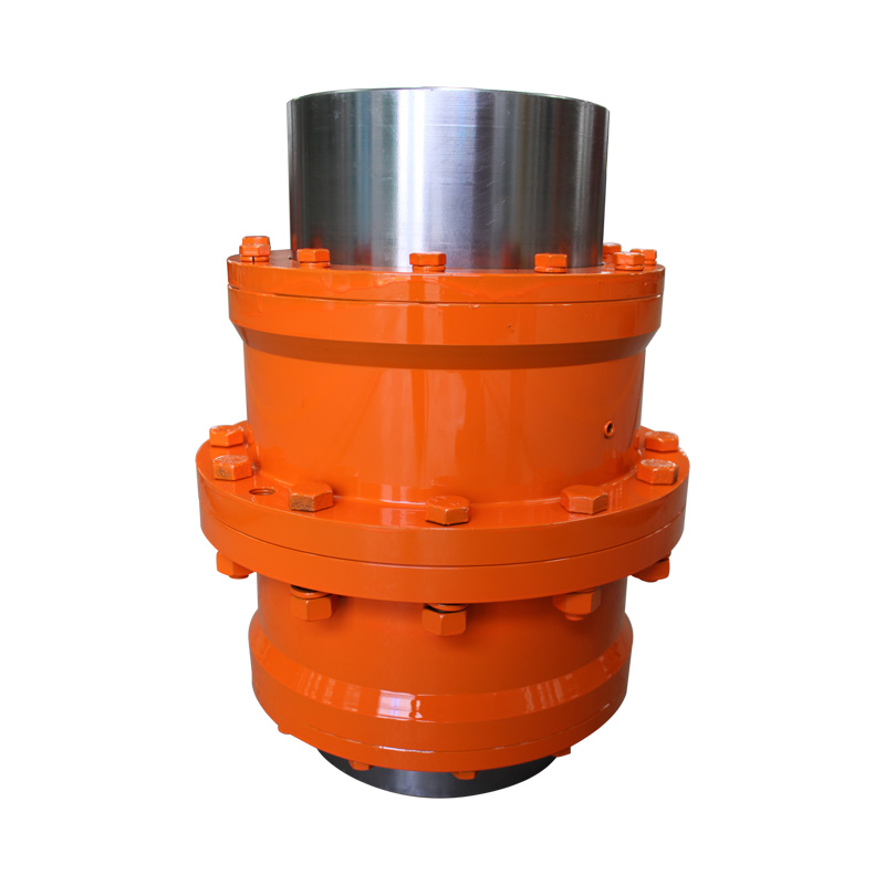
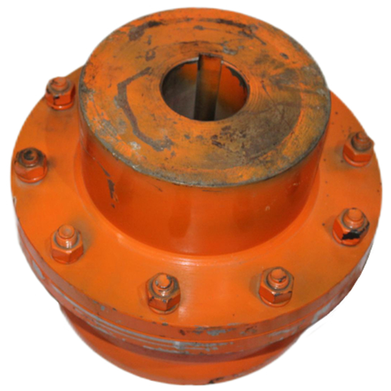
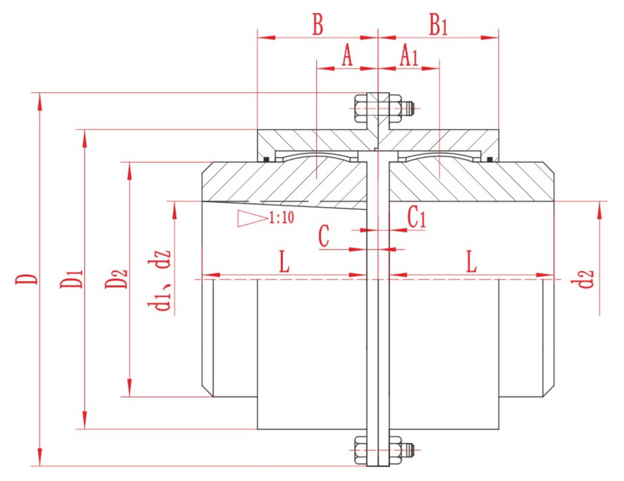
GICLZ crowned gear coupling with model-specific torque, bore and dimension tables, product photos and assembly drawing for preliminary selection.
Product Overview
The GICLZ Crowned Gear Coupling is a gear-coupling series for horizontal, coaxial shaft arrangements where the selected installation permits angular displacement. Its crowned-tooth geometry is presented with model-specific torque, speed, bore and dimensional data so engineers can compare the complete shaft interface and installation envelope. The series is also identified for applications where the distance between shaft ends is relatively long. The model table covers multiple nominal-torque sizes and lists an environmental range of −20 to +80 °C. Final model, bore form, lubrication, current manufacturing details and operating suitability must be confirmed from the actual duty and drawing.
Key Features
- Crowned gear coupling structure for horizontal coaxial shafts
- Model-specific nominal torque, speed, bore and dimensional data
- Source-defined angular-displacement application context
- Selection review includes shaft-end distance, bore form, lubrication and installation space
Typical Selection Context
- Horizontal coaxial drive lines with permitted angular displacement
- Drive lines where the distance between shaft ends requires review
- High-torque transmission duties within the published model range
Product Gallery
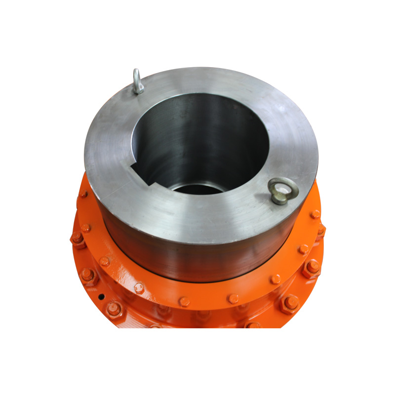
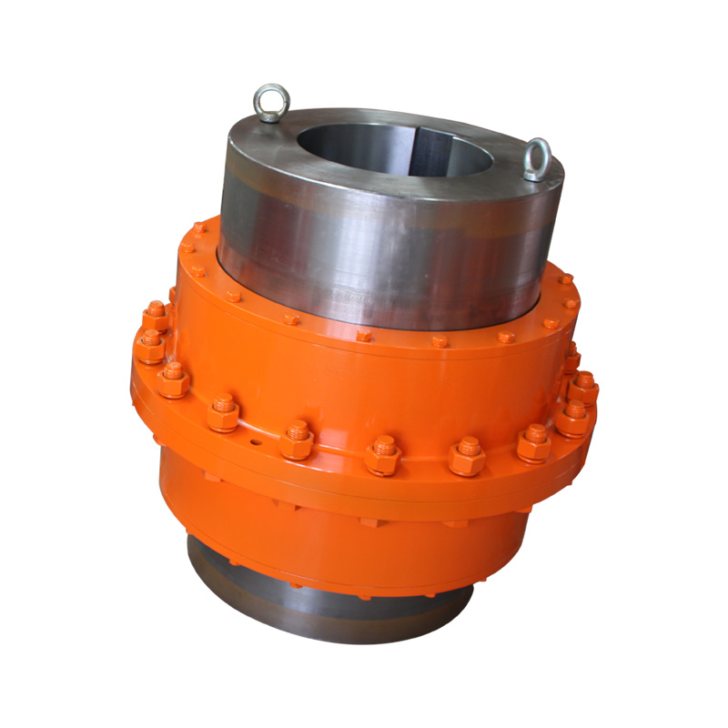
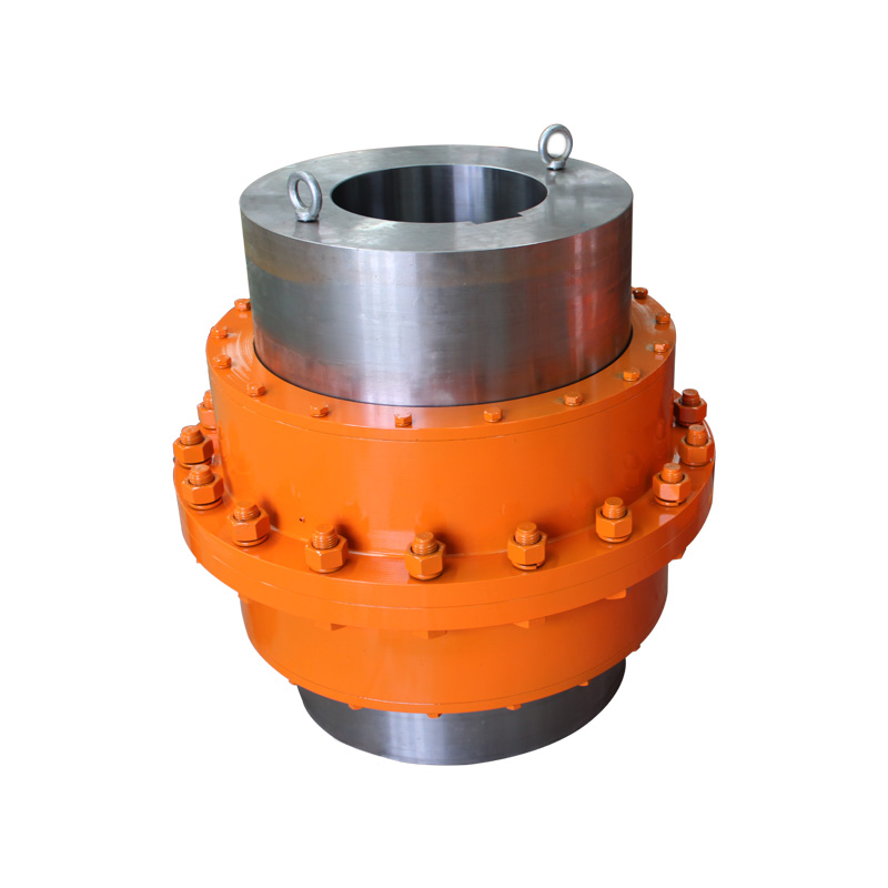
Technical Specification
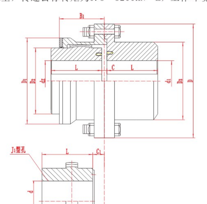
The following tables present the model and dimensional values available for preliminary comparison. Keep the relevant drawing with the selected row when reviewing a requirement.
| Model | Nominal torque Tn kN·m | Permissible speed [n] r/min | Bore diameter d dz | Bore length L Y J₁ | D | D₁ | D₂ | D₃ | B₁ | C | C₁ | Mass moment of inertia kg·m² | Mass kg |
|---|---|---|---|---|---|---|---|---|---|---|---|---|---|
| GICLZ1 | 0.8 | 7100 | ※ ※ 16~40~50 | 38~112 | 125 | 95 | 60 | 80 | 57 | 6.5/24 | 19 | 0.01 | 5.4 |
| GICLZ2 | 1.4 | 6300 | ※ ※ 25~50~60 | 44~142 | 144 | 120 | 75 | 95 | 67 | 8/16 | 18/19 | 0.02 | 10 |
| GICLZ3 | 2.8 | 5900 | ※ ※ 30~63~70 | 60~142 | 174 | 140 | 95 | 115 | 77 | 7 | 22/29 | 0.04 | 17 |
| GICLZ4 | 5.0 | 5400 | ※ ※ 32~71~80 | 60~172 | 196 | 165 | 115 | 130 | 89 | 8.5/19 | 22/42 | 0.07 | 23 |
| GICLZ5 | 8 | 5000 | ※ ※ 40~85~90 | 84~172 | 224 | 183 | 130 | 150 | 99 | 9.5 | 26/31 | 0.15 | 37 |
| GICLZ6 | 11.2 | 4800 | ※ ※ 48~95~100 | 84~212 | 241 | 200 | 145 | 170 | 109 | 9.5/11.5 | 26/41 | 0.24 | 47 |
| GICLZ7 | 15 | 4500 | ※ ※ 60~110~120 | 107~212 | 260 | 230 | 160 | 195 | 122 | 10.5 | 28/31 | 0.43 | 70 |
| Model | Nominal torque Tn kN·m | Permissible speed [n] r/min | Bore diameter d dz | Bore length L Y J₁ | D | D₁ | D₂ | D₃ | B₁ | C | C₁ | Mass moment of inertia kg·m² | Mass kg |
|---|---|---|---|---|---|---|---|---|---|---|---|---|---|
| GICLZ8 | 21.2 | 4000 | ※ ※ 65~120~130 | 107~252 | 282 | 245 | 175 | 210 | 132 | 12 | 28/41 | 0.61 | 82 |
| GICLZ9 | 26.5 | 3500 | ※ ※ 70~130~140 | 107~252 | 314 | 270 | 200 | 225 | 142 | 13/18 | 30/53 | 0.94 | 100 |
| GICLZ10 | 42.5 | 3200 | ※ ※ 80~150~160 | 132~302 | 346 | 300 | 220 | 250 | 165 | 14 | 30/51 | 1.67 | 150 |
| GICLZ11 | 60 | 3000 | ※ ※ 100~170~180 | 167~302 | 380 | 330 | 260 | 285 | 180 | 14 | 37 | 3 | 210 |
| GICLZ12 | 80 | 2600 | ※ ※ 120~190~200 | 167~352 | 442 | 380 | 290 | 325 | 208 | 14 | 37/65 | 5.3 | 284 |
| GICLZ13 | 112 | 2300 | ※ ※ 140~220 | 202~352 | 482 | 420 | 320 | 360 | 238 | 15 | 40/62 | 9.2 | 402 |
| GICLZ14 | 160 | 2100 | ※ ※ 160~240~250 | 242~410 | 520 | 465 | 360 | 410 | 266 | 16 | 40/50 | 16 | 582 |
| GICLZ15 | 224 | 1900 | ※ ※ 190~260~280 | 282~470 | 580 | 510 | 400 | 450 | 278 | 17 | 41/45 | 26 | 778 |
| GICLZ16 | 355 | 1600 | ※ ※ 200~300~320 | 282~470 | 680 | 595 | 465 | 500 | 320 | 16 | 45/65 | 47 | 1071 |
| GICLZ17 | 400 | 1500 | ※ 220~320 | 282~470 | 720 | 645 | 495 | 530 | 336 | 17 | 46/81 | 61 | 1210 |
| GICLZ18 | 500 | 1400 | ※ 240~340 | 330~550 | 775 | 675 | 520 | 540 | 351 | 16 | 48/53 | 82 | 1475 |
| GICLZ19 | 630 | 1300 | ※ 260~360 | 330~550 | 815 | 715 | 560 | 580 | 372 | 17 | 48/74 | 101 | 1603 |
| GICLZ20 | 710 | 1200 | ※ 280~380 | 380~550 | 855 | 755 | 585 | 600 | 393 | 20 | 51 | 140 | 2033 |
| GICLZ21 | 900 | 1100 | ※ 300~400 | 380~650 | 915 | 795 | 620 | 640 | 404 | 20 | 51 | 184 | 2385 |
| GICLZ22 | 950 | 950 | ※ 340~420 | 450~650 | 960 | 840 | 665 | 680 | 415 | 20 | 51 | 235 | 2452 |
| GICLZ23 | 1120 | 900 | ※ 360~450 | 450~650 | 1010 | 890 | 710 | 720 | 435 | 20 | 51/55 | 323 | 3332 |
| GICLZ24 | 1250 | 875 | ※ 380~480 | 450~650 | 1050 | 925 | 730 | 760 | 445 | 22 | 53/57 | 388 | 3640 |
| GICLZ25 | 1400 | 850 | ※ 400~500 | 540~650 | 1120 | 970 | 770 | 800 | 465 | 22 | 58 | 486 | 4073 |
| GICLZ26 | 1600 | 825 | ※ 420~530 | 540~650 | 1160 | 990 | 800 | 850 | 475 | 22 | 58 | 573 | 4527 |
| GICLZ27 | 1800 | 800 | ※ 450~560 | 540~800 | 1210 | 1060 | 850 | 900 | 479 | 22 | 58 | 789 | 5485 |
| GICLZ28 | 2000 | 770 | ※ 480~600 | 540~800 | 1250 | 1080 | 890 | 960 | 517 | 28 | 63 | 960 | 6050 |
| GICLZ29 | 2800 | 725 | ※ 500~630 | 540~800 | 1340 | 1200 | 960 | 1010 | 517 | 28 | 63 | 1269 | 7090 |
| GICLZ30 | 3500 | 700 | ※ 560~670 | 680~800 | 1390 | 1240 | 1005 | 1070 | 525 | 28 | 63 | 1822 | 9264 |
Technical Notes
- Model symbols, units and empty or placeholder cells are shown as published.
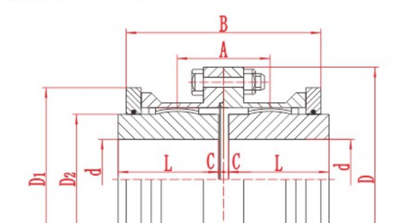
- Dimension letters must be interpreted with the relevant product drawing.
- Published values support preliminary review and do not replace final engineering confirmation.
Assembly Drawing
Referenced Standard
Referenced standard: JB/T 8854.3-2001 (previous designation ZBJ 19014-89). Current applicability and equivalence should be confirmed before ordering.
Information Required for Selection
- Driving and driven equipment
- Nominal, starting and peak torque; normal and maximum speed
- Shaft diameters, bore form, keyways and shaft-end distance
- Angular, radial and axial displacement requirements
- Lubrication, temperature, dust, corrosion and maintenance access
- Required quantity, destination and any inspection or documentation requirements
Product FAQ
What is the GICLZ coupling used for?
It is presented for horizontal coaxial shaft arrangements with permitted angular displacement and for drive lines where shaft-end distance must be reviewed.
Which values should be compared first?
Start with nominal torque, permissible speed, bore diameter, bore length, outside dimensions and the relevant drawing.
Can the model be selected by bore diameter alone?
No. Torque, speed, displacement, shaft-end distance, lubrication and installation space must also be checked.
Technical data is provided for preliminary selection. Confirm the final model, dimensions, materials, applicable standard and operating suitability with RONGXING DRIVE before quotation, manufacture or installation.