Technical Resources
Types of Coupling: Rigid and Flexible Shaft Couplings
The two main types of mechanical shaft coupling are rigid and flexible. A rigid coupling joins shafts without a flexible element and depends on the required alignment being maintained. A flexible coupling accommodates limited movement within the limi
The two main types of mechanical shaft coupling are rigid and flexible. A rigid coupling joins shafts without a flexible element and depends on the required alignment being maintained. A flexible coupling accommodates limited movement within the limits of the chosen design. Common flexible types include jaw, pin bush, grid, gear and disc or diaphragm couplings.
What is the difference between a rigid and a flexible coupling?
The main difference is how the coupling handles relative shaft movement. A rigid coupling joins two shafts in a fixed connection and depends on the machine keeping them within its specified alignment tolerance. A flexible coupling uses a compliant or articulated element to accommodate limited angular, parallel or axial movement, depending on its design.
| Check | Rigid coupling | Flexible coupling |
|---|---|---|
| Installation alignment | Align the shafts to the equipment and joint tolerances. | Align the shafts to the equipment and coupling tolerances. |
| Movement in service | Check whether the shaft and bearing arrangement can maintain the required alignment as the machines warm up. | Compare angular and parallel misalignment and axial movement with the limits for the selected size and duty. |
| Torsional behaviour | A rigid joint usually has high torsional stiffness. | Torsional stiffness and damping depend on the design. Check them separately from the misalignment rating. |
| Replacement fit | Check both shaft ends, hub fit, flange details and the bearing arrangement. | Check both shaft ends, shaft-end spacing, torque, speed and space to remove wear parts. |
Installation alignment and permitted movement in service answer different questions. Align the machines to the specified installation tolerances, then verify that the selected coupling can accommodate the expected movement during operation. For pump drives, the Hydraulic Institute’s pump FAQs describe ways to check shaft alignment.
Types of coupling and what to check
| Type | How it carries torque | Selection check |
|---|---|---|
| Rigid sleeve, split-muff or flange | A rigid connection between the shafts | Use where the machine design calls for a rigid joint and the shaft alignment and loads permit it. |
| Jaw or pin bush | An elastomer spider or resilient bushes transfer load | Check the insert grade, shock duty, shaft bores and space to replace the wear parts. |
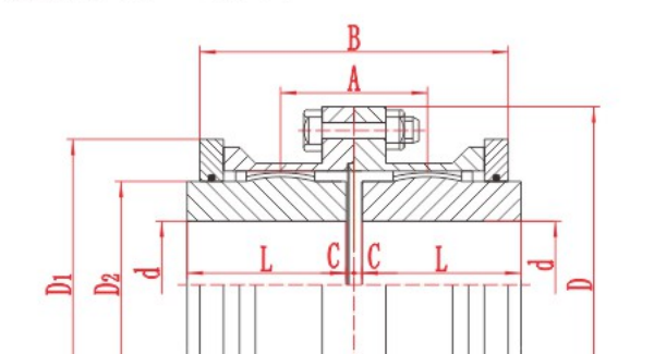
| Grid | A spring grid engages grooves in both hubs | Check the proposed size against peak torque, allowable movement, lubrication and cover access. |
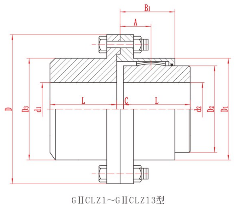
| Gear | External hub teeth mesh with internal sleeve teeth in a flexible gear coupling | Check the gear geometry, movement limits, bore capacity and lubrication requirements. |
| Disc or diaphragm | Metal discs or diaphragms flex as they transmit torque | Check axial movement, shaft spacing, arrangement and speed or balancing requirements. |
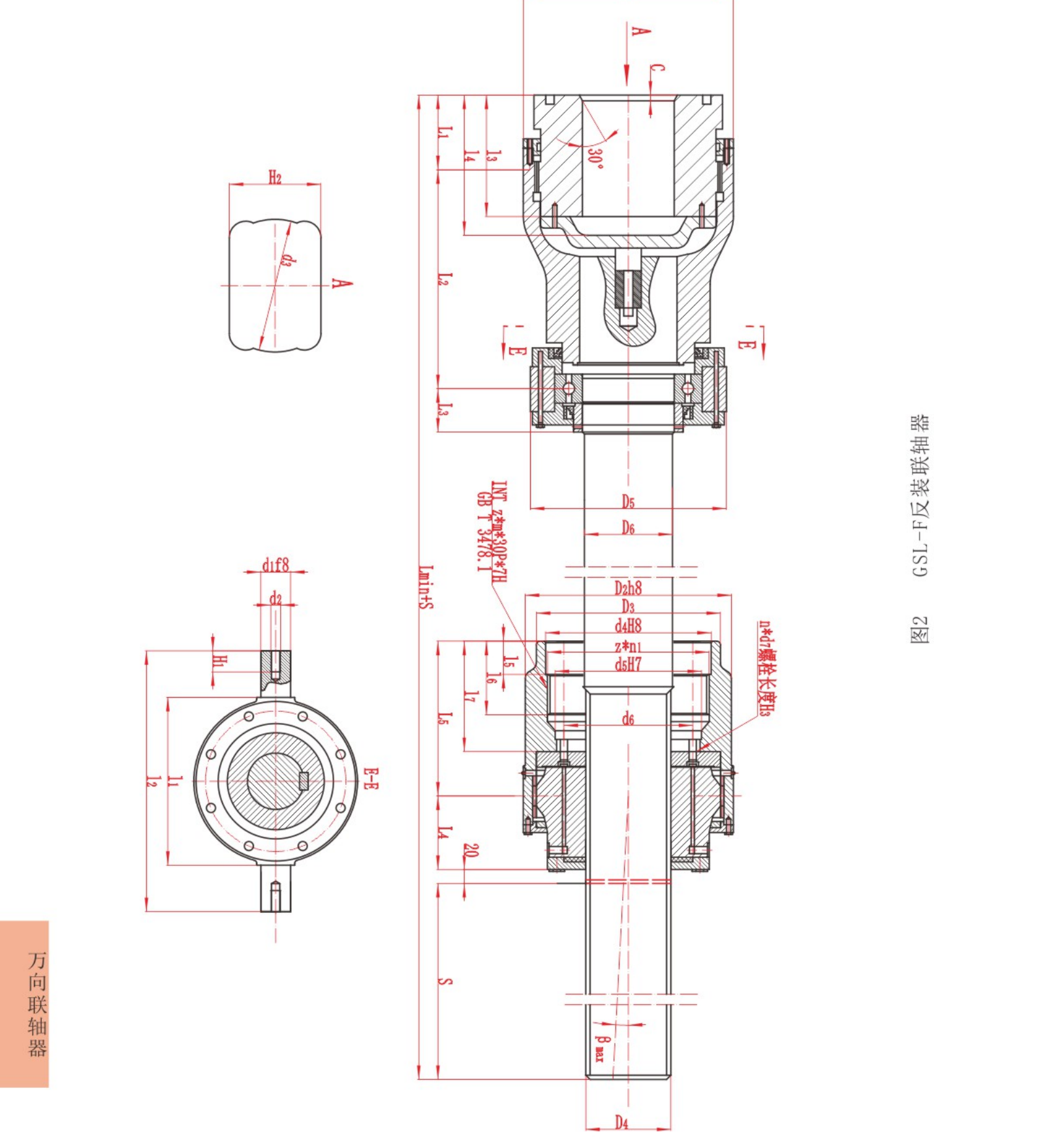
Universal-joint drives and fluid couplings serve different design needs. A cardan shaft uses universal joints to transmit torque between shafts that operate at an angle. A fluid coupling transfers torque hydrodynamically. Start with the machine layout and duty before comparing either with a close-coupled shaft connection.
When a rigid coupling makes sense
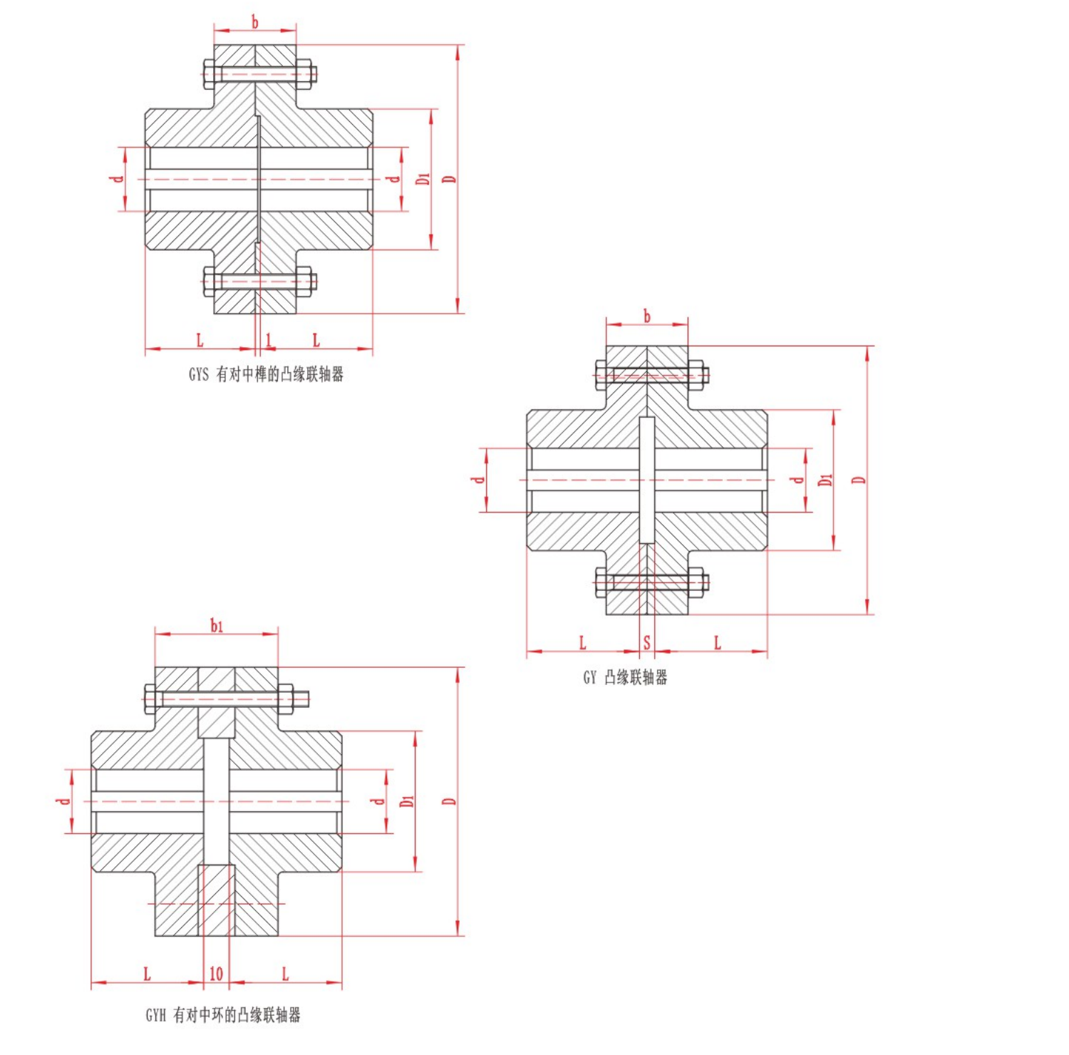
A rigid coupling is a candidate when the machine design requires a rigid joint and can maintain the specified alignment. Check bearing arrangement, shaft fits and expected movement as the equipment warms up. The RONGXING DRIVE GY Flange Coupling drawing shows a rigid flange arrangement. Compare the proposed shaft interfaces and assembly dimensions against the machine drawing.
When to compare flexible designs
Start with the angular and parallel misalignment the coupling must accommodate and the expected axial movement in service. Then check running and peak torque, operating speed and the space available for maintenance. Use the limits for the selected assembly under the actual duty. Align the shafts to the equipment and coupling makers’ installation tolerances. The Hydraulic Institute’s flexible coupling guide covers selection and installation considerations for pump systems.
For example, the RONGXING DRIVE JSA Grid Coupling drawing shows the spring-grid assembly and cover. Check access to the cover as well as bore and overall dimensions. For an elastomeric design, check the element material against the temperature and any oil or chemical exposure.
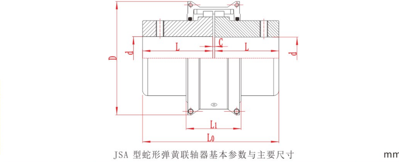
Shortlist a coupling for an industrial drive
First, identify the machines on either side of the joint and check their shaft-end drawings. Record both bore and keyway requirements, the distance between shaft ends and the clear space inside the guard. Then record transmitted power in kW, speed in r/min, any known peak loads, and starts or reversals. Check the shortlisted assembly against all these conditions before confirming a size.
For a pump, check whether the motor can move during seal service. See the centrifugal pump coupling guide for spacer and removal checks. For a jaw coupling replacement, compare the jaw profiles and spider arrangements. If you already know you need a crowned gear coupling, use the GICL gear coupling size chart to narrow the bore and envelope options.
For an installation or replacement in India, include the equipment drawings and any project-specified coupling requirements when you request a coupling review. State which parts must be removable without moving either machine.