Technical Resources
Gear Coupling Size Chart: GICL Dimensions and Bore Ranges
A gear coupling size chart helps you narrow the list by nominal torque, speed, shaft bore and available space. Start with the correct coupling series, then check both shaft ends against the drawing. A bore range tells you which sizes to investigate.
A gear coupling size chart helps you narrow the list by nominal torque, speed, shaft bore and available space. Start with the correct coupling series, then check both shaft ends against the drawing. A bore range tells you which sizes to investigate. The order drawing establishes the exact bore, fit and engagement length on each side.
GICL gear coupling size chart
The RONGXING DRIVE GICL crowned gear coupling catalogue lists 30 sizes. Dimensions are in millimetres. The bore and bore-length columns show catalogue ranges across the listed bore forms. Confirm the exact diameter and length pairing for the bore form you need. The catalogue limits the dz bore to 220 mm.
| GICL size | Nominal torque (kN·m) | Permissible speed (r/min) | Bore d/dz (mm) | Bore length L (mm) | Outside diameter D (mm) |
|---|---|---|---|---|---|
| GICL1 | 0.8 | 7100 | 16–38 | 38–82 | 125 |
| GICL2 | 1.4 | 6300 | 25–48 | 44–112 | 144 |
| GICL3 | 2.8 | 5900 | 30–60 | 60–142 | 174 |
| GICL4 | 5.0 | 5400 | 32–70 | 60–142 | 196 |
| GICL5 | 8 | 5000 | 40–80 | 84–172 | 224 |
| GICL6 | 11.2 | 4800 | 48–90 | 84–172 | 242 |
| GICL7 | 15 | 4500 | 60–100 | 107–212 | 260 |
| GICL8 | 21.2 | 4000 | 65–110 | 107–212 | 282 |
| GICL9 | 26.5 | 3500 | 70–125 | 107–212 | 314 |
| GICL10 | 42.5 | 3200 | 80–140 | 132–252 | 346 |
| GICL11 | 60 | 3000 | 100–160 | 167–302 | 380 |
| GICL12 | 80 | 2600 | 120–180 | 167–302 | 445 |
| GICL13 | 112 | 2300 | 140–200 | 202–352 | 482 |
| GICL14 | 160 | 2100 | 160–220 | 242–352 | 520 |
| GICL15 | 224 | 1900 | 190–250 | 282–410 | 580 |
| GICL16 | 355 | 1600 | 200–280 | 282–470 | 680 |
| GICL17 | 400 | 1500 | 220–300 | 282–470 | 720 |
| GICL18 | 500 | 1400 | 240–320 | 330–470 | 775 |
| GICL19 | 630 | 1300 | 260–340 | 330–550 | 815 |
| GICL20 | 710 | 1200 | 280–360 | 380–550 | 855 |
| GICL21 | 900 | 1100 | 300–380 | 380–550 | 915 |
| GICL22 | 950 | 950 | 340–400 | 450–650 | 960 |
| GICL23 | 1120 | 900 | 360–420 | 450–650 | 1010 |
| GICL24 | 1250 | 875 | 380–450 | 450–650 | 1050 |
| GICL25 | 1400 | 850 | 400–480 | 540–650 | 1120 |
| GICL26 | 1600 | 825 | 420–500 | 540–650 | 1160 |
| GICL27 | 1800 | 800 | 450–530 | 540–800 | 1210 |
| GICL28 | 2000 | 770 | 480–560 | 540–800 | 1250 |
| GICL29 | 2800 | 725 | 500–600 | 540–800 | 1340 |
| GICL30 | 3200 | 700 | 560–630 | 680–800 | 1390 |
Source: RONGXING DRIVE GICL product catalogue, pp. 04–05. The nominal torque and permissible speed are separate catalogue values. Ask for a duty review if the drive has high starting torque, frequent reversals, shock loads or significant misalignment. Confirm the permissible combination of load, speed and movement for the proposed assembly.
Read the drawing before checking fit
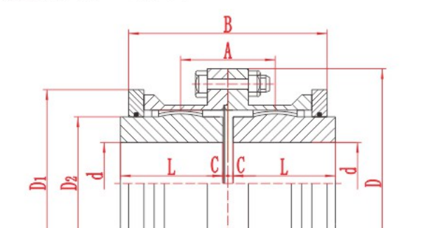
GICL assembly drawing. Use the drawing for the proposed bore form and hub arrangement when checking installation dimensions.
The bore diameter and the shaft diameter describe the mating surfaces. Record the shaft diameter, fit, keyway and usable engagement length on the driving and driven sides separately. If the two shaft ends differ, show both in the enquiry.
On the GICL drawing, D is the large outside diameter of the assembly. Check the clearance to the guard and nearby equipment, including space for assembly and maintenance. The bore length L, the axial dimension B and the drawing dimension C refer to different features. Measure the distance between shaft ends from one shaft end face to the other and identify it on the installation sketch. Use the drawing to confirm how this distance relates to the selected hub arrangement.
Worked example with two different shaft diameters
Suppose the driving shaft is 55 mm, the driven shaft is 65 mm, and the clear radial envelope allows a coupling outside diameter of 210 mm. GICL3 has a listed bore range of 30–60 mm, so the 65 mm shaft takes it off the shortlist. GICL4 has a listed range of 32–70 mm and D of 196 mm, so it remains a candidate at this stage. GICL5 has D of 224 mm and exceeds the envelope.
Before selecting GICL4, confirm that both bores are available in the required forms and lengths. Check the keyways, hub orientation, shaft-end separation and guard clearance. Then check whether the application torque, speed and shaft movement are within the approved limits. This example uses assumed shaft dimensions and gives a dimensional shortlist only.
Check a replacement before ordering
Start with the old assembly drawing or nameplate, if available. Send a sketch that identifies the two shaft ends and where each measurement was taken. For a complete replacement, check both hubs and the installed envelope. For a hub or sleeve replacement, the supplier also needs the mating tooth geometry, flange interface and sealing arrangement. A matching size number or outside diameter alone leaves those interfaces unverified.
For an Indian steel plant, include the purchase specification and revision if the plant cites one. For example, IPSS 1-01-005-18 covers gear-type flexible couplings for steel-industry use and gives separate details for its Type A and Type B designs. Ask for a drawing and a written check against the purchase specification when it applies.
For a gear coupling enquiry, send the shaft-end drawings, operating speed, continuous and peak torque where known, shaft-end separation and available clearance. If the installation needs a different hub layout, browse the RONGXING DRIVE gear coupling range and include the layout in your enquiry.