Technical Resources
Can the maximum torque, speed and operating angle of a cardan shaft be used at the same time?
Can cardan shaft maximum ratings be combined? Learn how buyers in India should check torque, speed, joint angle, shaft length and duty together.
Do not assume that they can. A cardan shaft’s maximum torque, maximum speed and maximum operating angle may have different rating conditions. They can be used together only when the manufacturer confirms that combination for the exact assembly, installed length, joint arrangement and duty cycle. Passing three separate catalogue checks does not establish an approved operating condition.
For industrial buyers in India, the practical task is to specify the torque, speed and angle that occur together during each part of the machine cycle. Then have those combinations assessed against the proposed shaft, including its connections, length compensation, lubrication and environment.
Why three catalogue maxima are not a complete operating specification
There are two possible sources of confusion. First, a product-family overview may combine values from different shaft sizes or configurations. Those values do not all describe one assembly. Second, even values published for one size may refer to different conditions or different types of limit.
For example, an angle entry does not necessarily establish continuous operation at that angle under the highest stated torque and speed. Likewise, an assembly’s speed suitability cannot be established without considering its length and installation. Read the definitions and qualifications next to each rating, rather than treating the largest numbers as independent permissions.
| Published item | What to establish | What the entry alone does not prove |
|---|---|---|
| Rated torque | Rating definition, model and applicable duty | Suitability for every peak, reversal or repeated load |
| Fatigue torque | Definition and loading basis used for that rating | An interchangeable value for rated or maximum torque |
| Maximum or peak torque | Permitted event, duration, frequency and conditions | Continuous operation at the same torque |
| Maximum speed | Exact assembly length, joint angles and relevant dynamic limits | Acceptable operation at every length, angle and load |
| Operating angle | Angle at each joint, movement range and applicable rating conditions | Approval to run continuously at maximum torque and speed |
| Length compensation | Permitted connected length range and engagement requirements | Suitability at every extension under every operating condition |
The complete selection must satisfy the applicable conditions together. An entry missing a definition or a combined operating limit needs clarification before it can be used to approve a drive.
How operating angle and speed interact
A single cross-type universal joint operating at an angle produces a varying output speed even when its input speed is constant. Increasing the joint angle changes that variation. The Virtual Labs universal-joint theory resource explains this distinction between continuous torque transmission and constant-velocity transmission.
In a correctly arranged pair of universal joints, the output speed variation can be compensated under the appropriate geometry and phasing conditions. That does not remove all internal motion or loading. A double Cardan simulation example illustrates matching input and output speeds while the intermediate shaft speed still varies.
For an industrial shaft, provide the angle at both joints, the relationship between the driving and driven axes, and how the geometry changes during operation. An angle measured in one position may not describe a moving installation. Ask for an assessment of the proposed torque and speed at each relevant joint-angle combination.
Do not apply a universal angle cut-off or copy another shaft’s speed-times-angle limit. Such limits require the appropriate product data and selection method. A smaller operating angle may help a particular installation, but it does not by itself approve the shaft’s torque, speed or service life.
Torque needs a load history, not just a maximum number
Separate normal running torque from startup, braking, reversing, shock and repeated cyclic loads. State the duration and frequency of those events, and identify where the shaft sits relative to the gearbox and driven machine.
RONGXING DRIVE’s SWC-BF telescopic flanged cardan shaft tables distinguish rated torqueTn and fatigue torque Tf. These headings describe different rating fields; neither should be relabelled as the buyer’s measured peak torque. The table and drawing provide inputs for comparison, while the proposed operating duty still needs confirmation.
Keep units explicit. 1 kN·m equals 1,000 N·m. A unit error can change the apparent torque by a factor of a thousand. If torque is calculated from mechanical power and speed, identify the shaft location, operating state and assumptions. A steady-running estimate does not establish startup or stall torque, and a power-divided-by-speed calculation must not be applied at zero speed.
A general safety margin cannot replace the combined assessment. Ask which selection factors are used, what they cover and how repeated loading is evaluated for the selected model. There is no basis for applying the same percentage to every industrial cardan shaft.
Shaft length and the complete drivetrain also matter
Speed assessment includes the actual shaft assembly and its installation. For a long shaft, ask whether bending critical speed needs to be checked over the operating length range. For a drive with fluctuating loads or a broad speed range, ask whether a torsional assessment is needed for the complete drivetrain.
Balancing is a separate requirement. A statement that a shaft is balanced does not establish that all operating speeds avoid an unacceptable dynamic condition. Agree the balancing requirement and the applicable operating-speed limits for the proposed assembly.
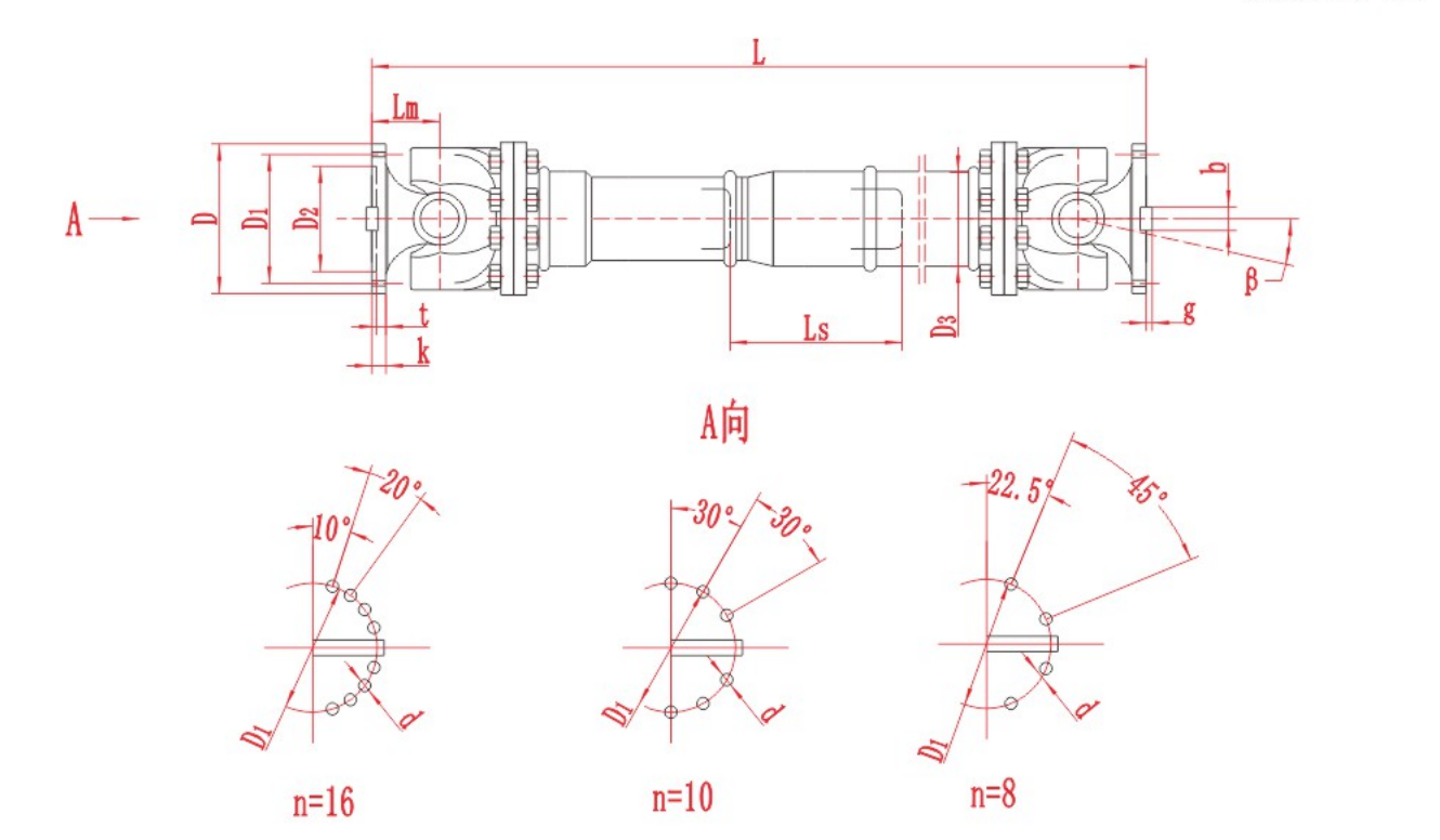
SWC-BF assembly drawing. Overall length L, length compensation Ls and joint angle β describe different aspects of the installation. The angles in the flange-hole layouts below the assembly are hole-spacing angles. This drawing identifies geometry; it is not a combined torque–speed–angle approval chart.
State the normal installed length and the required shortest and longest connected positions. Keep separate the positions used only for supported, disconnected handling or maintenance. Confirm the required engagement, clearances and installation setting from the approved drawing; do not assume the shaft must always be installed at the midpoint of its travel.
Also include the end connections, equipment supports, rotating clearance, temperature and contamination conditions. A suitable joint rating cannot compensate for an unsuitable flange connection or installation arrangement.
Record which operating values actually occur together
Consider the following hypothetical machine duty. These numbers are illustrative inputs, not RONGXING DRIVE product ratings or approved operating points. The angle shown is for one joint; an actual enquiry must describe both joints and the installation length in each state.
| Machine state | Shaft torque (kN·m) | Shaft speed (r/min) | Joint angle (°) | Duration or frequency to specify |
|---|---|---|---|---|
| Normal production | 8 | 600 | 4 | Continuous running hours |
| Faster production mode | 4 | 1,200 | 4 | Time spent in this mode |
| Production at an adjusted machine position | 6 | 500 | 9 | Time at this position and movement details |
| Startup event | 12 | 0–150 | 4 | Assumed 2-second event; starts per hour still required |
In this example, the largest individual inputs are 12 kN·m, 1,200 r/min and 9°. Combining those three maxima creates a condition that is not represented by any row. Checking only normal production would also omit important operating states.
Submit the complete duty table and explain whether transitions or abnormal events can make the peaks overlap. If the three maxima can genuinely occur together, include that combination explicitly. If they cannot, document the machine conditions that prevent coincidence.Neither case removes the need to assess every required operating state and transition.
The example does not demonstrate that any particular shaft will pass. It shows how to communicate the load combinations that need evaluation.
What should a manufacturer confirm before the shaft is ordered?
Request a written proposal linked to the exact model, configuration and assembly drawing. The technical confirmation should identify:
The accepted operating combinations: torque, speed, both joint angles, connected lengths and the duty cycle considered.
The rating basis: definitions of rated, fatigue and permitted peak torque, with any applicable selection or correction factors.
Dynamic requirements: relevant speed restrictions, balancing requirements and any required drivetrain review.
Installation conditions: both interfaces, clearances, movement limits and the approved arrangement of the joints.
Service conditions: lubrication instructions, access, temperature and contamination assumptions, together with inspection and maintenance requirements.
If a proposal lists only separate maximum figures, ask for the missing combined assessment. Do not invent a derating curve or assume that a maximum mechanical angle is automatically a continuous working angle.
If a required combination is outside the confirmed conditions, discuss changes with the supplier and machine engineer. Options may include another shaft size or configuration, revised geometry, reduced speed or a different operating duty. Increasing shaft size alone is not proof that the complete installation will pass.
Preparing an enquiry for an industrial drive in India
Send a duty table, the machine layout, both connection drawings and the required length range. Include motor and gearbox information, available torque measurements, startup and braking events, reversals, daily operating hours, environmental conditions and maintenance access. Mark unknown inputs clearly so that assumptions can be agreed.
The quotation data guide for Indian cardan shaft buyers provides a fuller input checklist. If the series is still undecided, use the SWC and SWP configuration comparison to separate construction and length-compensation choices from operating-duty verification.
RONGXING DRIVE’s cardan shaft range includes configurations that can be compared against those requirements. Send the operating combinations and installation drawings and request confirmation for the proposed assembly. The country of installation does not replace the need to specify the actual plant conditions.
Frequently asked questions
Can all three maximum values ever be used simultaneously?
They may be used together only if that combination is explicitly confirmed for the exact shaft assembly and duty. Separate catalogue maxima do not establish that permission. There is no universal rule that the three maxima must always be compatible or always be incompatible.
Does reducing torque allow operation at any speed and angle?
No. Reduced torque does not remove joint geometry, speed, dynamic, lubrication or installation limits. The revised combination still needs to fall within the confirmed operating conditions.
Does a double-joint arrangement remove the speed limitation?
No. Suitable geometry and phasing can compensate output speed variation, but intermediate shaft motion and assembly-specific dynamic limits still need consideration. The number of joints is not a substitute for a speed assessment.
Is a catalogue operating angle sufficient for continuous service?
Only when the rating conditions support the proposed continuous duty. Confirm the torque, speed, both joint angles, length and service conditions together. Do not infer continuous capability from an isolated angle entry.