Technical Resources
How do I select an industrial cardan shaft for a rolling mill in India?
Select an industrial cardan shaft for a rolling mill in India: assess peak torque, speed, joint angles, telescopic travel, flange fit and maintenance before ordering.
Select an industrial cardan shaft for a rolling mill in India by checking the load at the actual shaft position, repeated and peak torque, speed range, joint angles, working length, telescopic movement and both end connections together. Then confirm lubrication, inspection and replacement requirements for the plant. Motor power, a flange diameter or a familiar series name alone cannot establish suitability.
Start with the mill stand and its operating cycle. A roughing stand, finishing stand and roller-table drive should not be treated as the same application simply because all three belong to a rolling mill.
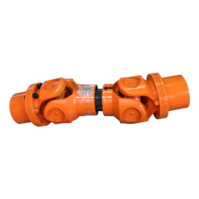
Figure 1. RONGXING DRIVE SWC-BH Telescopic Welded Cardan Shaft. This assembly view shows both universal joints, the central shaft section and the end connections. Use the matching drawing for dimensions; the photograph does not establish a torque rating or suitability for a particular mill stand.
1. Define the rolling duty before choosing a shaft series
Identify whether the shaft drives a work roll, pinch roll, coiler or another part of the line. Record hot or cold rolling, reversing or one-direction operation, and the positions reached during roll adjustment and replacement.
For each relevant operating condition, provide:
Mechanical power and rotational speed at the cardan shaft.
Normal rolling torque, transient peaks and how frequently they occur.
Starting, braking, reversing and overload conditions.
Required operating hours and planned maintenance opportunities.
Installation geometry at normal and extreme equipment positions.
In a drive with multiple output shafts, establish how torque is distributed. Do not assign the full motor torque to every shaft, or assume equal sharing, without checking the drivetrain arrangement.
Keep the operating data and the installation drawing in the same enquiry. This allows the proposed shaft to be assessed against both its rolling duty and its physical arrangement.
2. Separate mean torque, peak torque and repeated loading
When mechanical shaft power and speed are known, calculate the corresponding mean torque:
T_mean (N·m) = 9,550 × P_shaft (kW) / n_shaft (r/min)
Power and speed must refer to the same shaft location. For a shaft downstream of a reducer, use the transmitted power and speed at that shaft, rather than mixing motor speed with output-side data. The coefficient follows from the mechanical relationship between power, torque and angular speed.
A preliminary example
Assume, purely for illustration, that a cardan shaft transmits 250 kW at 150 r/min:
T_mean = 9,550 × 250 / 150 ≈ 15,917 N·m = 15.9 kN·m
This calculation gives the torque corresponding to the assumed steady power and speed. It does not determine the steel-biting peak, reversing load, fatigue requirement or final shaft size. At standstill, the power-over-speed calculation is not a valid way to determine starting torque.
For a rolling-mill selection, review three distinct questions:
| Load check | Information to obtain |
|---|---|
| Normal operation | Torque and speed during the intended rolling schedule |
| Repeated loading | Load levels, durations, cycle counts and any torque reversals |
| Exceptional events | Starting, braking, biting, overload and protection settings, with event duration and frequency |
The product tables for the RONGXING DRIVE SWC-BH and SWC-BF list rated torque Tn and fatigue torque Tf separately. Neither should be renamed “maximum peak torque” or substituted for the other. Ask for the rating definitions and application assessment for the proposed model.
If an application factor is used, agree its basis with the shaft supplier and mill engineer. A single percentage allowance applied to every rolling-mill drive does not replace a review of the actual load cycle. Record the assumptions behind any factor and ask which operating conditions it covers.
3. Review speed, joint angles and phasing as one arrangement
Specify the minimum, normal and maximum shaft speeds, together with the operating angle at each universal joint. Include changes caused by roll movement, adjustment and the installation geometry.
The largest angle in a catalogue is not permission to use that angle at every speed and torque. Ask the supplier to confirm the proposed speed–angle combination, shaft length, joint arrangement and phasing. Where the geometry changes in two planes, provide both plan and elevation drawings.
For long or fast-running assemblies, include shaft length, support arrangement and the full speed range in the technical enquiry. Ask the supplier and mill engineer whether a critical-speed or torsional assessment is needed for the complete drivetrain, and agree the balancing requirement for the proposed assembly.
A useful selection drawing shows the gearbox output axis, roll axis, joint centres and the range of equipment movement. A single photograph of a stationary installation rarely provides all of that information.
4. Check working length, telescopic travel and the roll-change position
Measure length between the reference planes identified on the proposed assembly drawing. Record the operating positions separately from any disconnected or supported position used for roll replacement.
Ask the supplier to verify:
The shortest and longest working connection distances.
The permitted installed position within the telescopic range.
Required spline engagement and the limits against overextension or bottoming.
Any additional movement needed during assembly or roll change.
The space required for the rotating joint, guards and maintenance access.
Working length and available telescopic travel are different quantities. A shaft that has enough total travel may still be unsuitable if the normal installation position leaves insufficient movement in one direction.
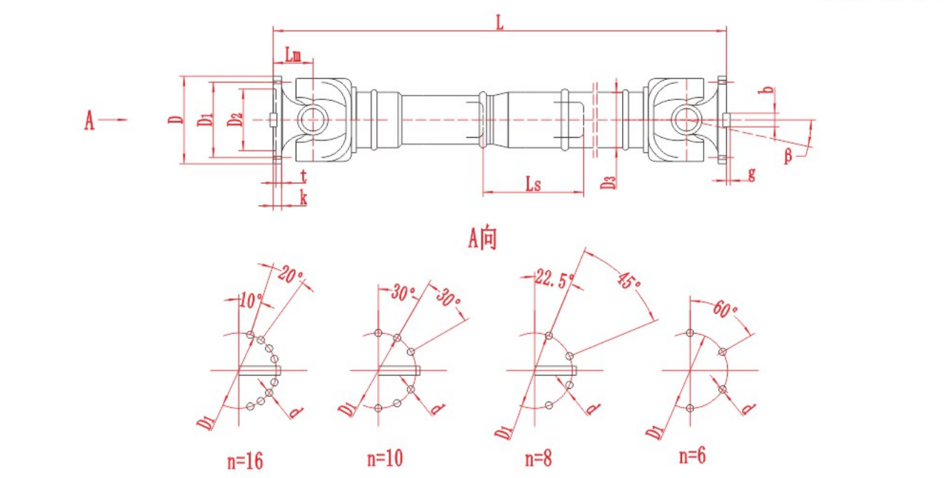
Figure 2. SWC-BH assembly drawing. Read L, Ls, β and the connection dimensions with the matching model table. The lower diagrams describe flange-hole arrangements, not permissible operating angles.
Use the drawing to identify the specified length L, length compensation Ls and joint angle β before comparing candidates. Confirm the definition and reference position of each dimension for the proposed model. Do not scale a dimension from this illustration or treat the drawing as approval of a particular installation.
A telescopic design is a candidate where the connection distance must vary. A non-telescopic design requires the complete system to address any necessary axial movement elsewhere. The correct choice follows the installation, not a rule that every rolling mill needs the same shaft construction.
5. Verify both interfaces and the rotating envelope
A replacement shaft must match more than the outside diameter of an existing flange. Compare the drawings for both the gearbox and roll-side connections.
| Interface or space requirement | What to confirm |
|---|---|
| Locating features | Pilot/spigot diameter, fit and locating depth |
| Fasteners | Bolt circle, hole count, hole diameter and approved fastener specification |
| Torque-transfer features | The actual face key, serration, friction or other connection design |
| Rotating space | Joint swing diameter and clearance throughout equipment movement |
| Installation access | Tool space, lifting arrangement and removal route |
Do not assume that “welded” means the shaft has no end flanges, or that “flanged” guarantees compatibility with an existing connection. These terms describe configurations; the specific assembly and mating drawings determine fit.
If the old shaft has failed repeatedly, add the failure history to the enquiry. Copying its dimensions may reproduce an unsuitable selection.
6. Compare RONGXING DRIVE candidates against the completed duty sheet
The following configurations provide starting points for technical comparison, rather than automatic recommendations for a mill stand:
| RONGXING DRIVE configuration | When to include it in the comparison | What still needs confirmation |
|---|---|---|
| SWC-BH Telescopic Welded Cardan Shaft | The installation requires an operating angle and length compensation | Load cycle, rated/fatigue checks, speed–angle combination, length and both interfaces |
| SWC-BF Telescopic Flanged Cardan Shaft | A telescopic flanged configuration is relevant to the proposed layout | The same duty checks, plus the specific structural and connection dimensions |
RONGXING DRIVE’s broader range includes SWC and SWP configurations. Compare their actual records and drawings rather than assuming that one series is always stronger, easier to maintain or interchangeable with another supplier’s shaft.
For the general sizing process beyond rolling-mill applications, see Industrial Cardan Shaft Sizing and Universal Joint Shaft Selection.
7. Specify the site and procurement requirements for India
For a project in India, record the conditions at the actual mill: temperature near the joints, scale, dust, water exposure, cleaning practices, running schedule and access during shutdowns. Avoid specifying a grease, sealing arrangement or lubrication interval from the country name alone.
Before ordering, request written agreement on the approved drawing, applicable technical specifications, inspection records, lubrication instructions, spare-part identification and packaging. Confirm the delivery destination, purchasing responsibilities and support arrangements for the particular order. Do not assume local stock or on-site service from a supplier’s general international marketing.
Access for greasing and inspection should be considered while selecting the shaft and guarding arrangement. Maintenance must follow the approved instructions, with the drive isolated; do not inspect an exposed rotating shaft. Obtain the installation, guarding and lubrication instructions issued for the selected RONGXING DRIVE assembly before putting it into service.
Prepare your rolling-mill cardan shaft enquiry
Send RONGXING DRIVE a dimensioned layout and the following information:
Mill type, stand position and whether the duty reverses.
Mechanical shaft power, speed range, normal torque, peak torque and load cycle.
Both joint angles and their variation through the operating positions.
Working length range, required telescopic movement and roll-change arrangement.
Drawings of both connections, rotating clearance and available installation space.
Environmental exposure, maintenance access and any previous failure symptoms.
Quantity, destination in India, required documentation and planned shutdown date.
Request a preliminary technical review. Identify any measurements or load data that are still missing. Final model selection and operating suitability should be confirmed against the agreed duty, current product information and approved drawings before manufacture or installation.
Frequently asked questions
Can I select a rolling-mill cardan shaft from motor power alone?
No. Power and speed at the shaft provide a mean torque calculation. Final selection also requires peak and repeated loads, joint angles, shaft length, movement, connection details and the operating environment.
Does a larger catalogue torque rating guarantee a better replacement?
No. The rating definition and load cycle must be compatible, and the assembly must fit the installation. A larger joint can introduce different dimensions, mass and clearance requirements.
Is there one suitable cardan shaft size for rolling mills in India?
No. Country identifies the project market, not the mechanical duty. Select the shaft for the particular stand, load cycle, geometry and site conditions, then confirm the purchasing and support requirements for that Indian installation.