Technical Resources
Gear Coupling Types Explained: Full vs Half, How They Work, and What to Specify
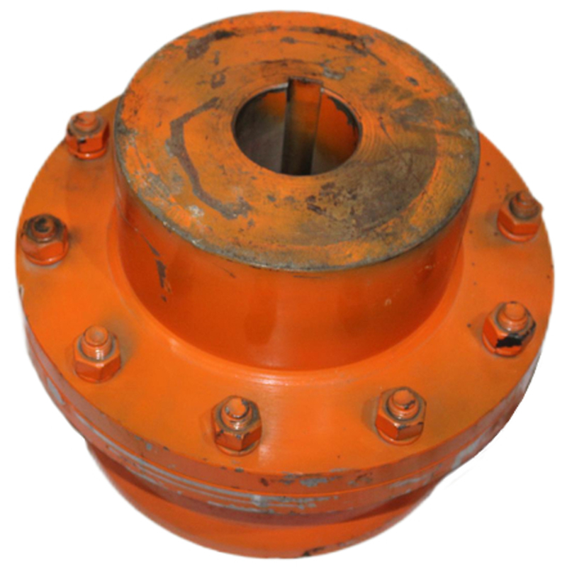
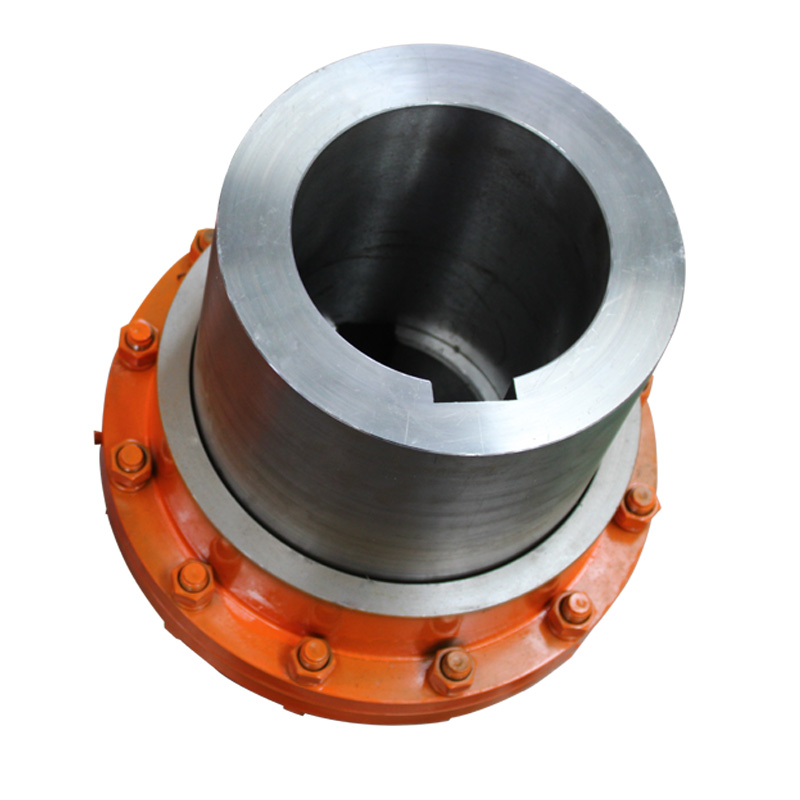
A full gear coupling has two flexible gear meshes, one at each end. A half gear coupling, often called a flex-rigid coupling, has one flexible gear mesh and one rigid connection. When a purchase order says “half gear coupling”, check the drawing and the scope of supply. The term can also refer to a single flexible half sold as a component.
A full gear coupling has two flexible gear meshes, one at each end. A half gear coupling, often called a flex-rigid coupling, has one flexible gear mesh and one rigid connection. When a purchase order says “half gear coupling”, check the drawing and the scope of supply. The term can also refer to a single flexible half sold as a component.
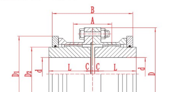
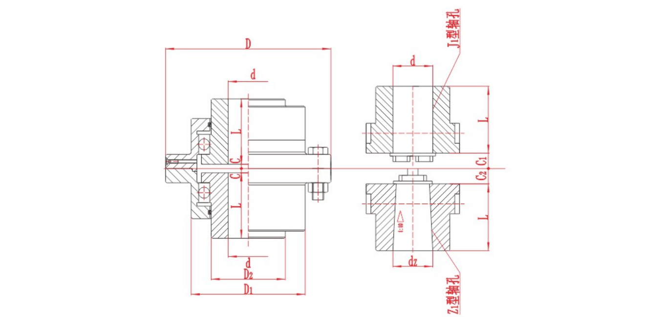
RONGXING DRIVE GICL assembly drawing. Use the drawing with the selected size row to check the bore, flange and installation envelope.
Difference between full gear coupling and half gear coupling
| Check | Full gear coupling (flex-flex) | Half gear coupling (flex-rigid) |
|---|---|---|
| Flexible gear meshes | Two | One |
| Shaft movement | Two flex planes can accommodate parallel offset as well as angular misalignment, within the design limits | The single flex plane accommodates angular movement at that mesh. Review the entire shaft line if parallel offset is required |
| Drawing check | Locate both flex planes and verify shaft-end spacing, both bores and the flange envelope | Identify the flexible end and confirm the pilot, bolt circle and mating face on the rigid end |
| Replacement check | Confirm the sleeve, hub and flange arrangement at both ends | Confirm whether the order covers a flexible half alone or a complete flex-rigid assembly |
Sleeve construction is a separate choice. A continuous sleeve spans both hubs in one piece. A flanged-sleeve assembly joins two sleeve flanges, so check the joint diameter and the space needed to reach the bolts. A spacer changes the distance between coupling ends for a particular shaft layout or maintenance clearance. A telescopic design addresses specified axial movement. A brake-drum design adds a braking surface. Specify the number of flexible meshes separately. The Hydraulic Institute lists both close-coupled and spacer gear coupling arrangements.
Gear coupling working principle
The driving shaft turns an externally toothed hub. Its teeth mesh with the internal teeth of a sleeve and transmit torque into the sleeve assembly. In a common bolted full gear coupling, torque crosses the sleeve flanges, passes through the second gear mesh and reaches the driven shaft. In a flex-rigid assembly, the second connection is rigid.
Crowned external teeth let the hub and sleeve operate at a small angle to each other as the teeth remain engaged. Relative movement at the tooth surfaces makes lubrication important. The seals help retain lubricant. Use the selected model’s instructions for alignment, lubricant, quantity and maintenance interval, and verify the allowable combination of torque, speed and displacement. Hydraulic Institute pump FAQs
Gear coupling parts and what they do
| Part name | Function |
|---|---|
| Externally toothed hub | Fits the shaft and transfers torque to or from the sleeve through the tooth mesh |
| Internally toothed sleeve | Encloses the hub teeth and carries torque through the coupling body |
| Flange bolts and nuts, where fitted | Join mating flanges in bolted designs |
| Hub-to-sleeve seal | Retains lubricant where the hub passes through the sleeve |
| Flange gasket, where fitted | Seals the joint between mating faces |
| Lubrication plug or fitting, where fitted | Provides access to the lubricant cavity |
| Key, where specified | Transfers torque between a keyed shaft and hub |
For spare parts, send the model, size, drawing revision and item number. Include a photo if the marking is unclear. For a sleeve or hub replacement, confirm the tooth geometry and mating part as well as the shaft fit.
What to include in a gear coupling material specification
Specify the material by component. Ask the supplier to identify the grade and governing standard for the toothed hub and sleeve separately, along with any specified heat treatment and hardness. A general description such as “steel coupling” leaves those requirements open.
| Component | Details to confirm on the drawing or purchase specification |
|---|---|
| Toothed hubs and sleeves | Grade and standard for each part, heat treatment, hardness range and test location. If the design calls for surface hardening, specify the required case depth and acceptance method |
| Rigid flange or spacer, if used | Material grade, interface dimensions and any inspection requirements |
| Fasteners | Property class or material specification and approved tightening instructions |
| Seals and gaskets | Material compatible with the lubricant and service temperature |
| Documentation | Material certificates, heat-treatment records or inspection reports required by the purchase order |
How to find the right gear coupling size
Select the coupling configuration first. Use the manufacturer's size table to screen for the required torque at operating speed, then check each bore and shaft fit separately. Compare the selected assembly drawing with the measured shaft-end gap, flange clearances and room for maintenance. Ask the supplier to verify how speed, torque and misalignment combine at the selected size.
How to specify a replacement gear coupling
Start with the installed drawing and mark the flex planes, shaft-end gap and mating interfaces. On a mill or conveyor drive, include starting, reversing or shock loads if present. Send continuous and peak torque in N·m or kN·m, operating and maximum speed in r/min, both shaft diameters and usable engagement lengths in mm, and the expected angular, parallel and axial movement. Include the available guard space, operating temperature, and any restrictions on access for lubrication.
The GICL Crowned Gear Coupling provides an assembly drawing and size-specific tables for preliminary review. Use the drawing to interpret the dimensions in the selected row. Before ordering, ask RONGXING DRIVE to confirm the shaft fits, material requirements and combined operating conditions for that size.