Technical Resources
How should I compare gear and grid couplings for a drive with shock loads?
Use the same torque history, installation dimensions and maintenance constraints to compare gear and grid couplings for a shock-loaded drive.
Shortlist a grid coupling when torsional compliance is important, and a crowned gear coupling when high torque within a tight diameter is the main constraint. Compare specific sizes against the same duty, including the magnitude, duration and frequency of torque peaks. Where the aim is to reduce the shock reaching a gearbox or another component, ask for stiffness data and check the response of the whole drive.
How each coupling carries a shock load
In a grid coupling, a steel spring grid bridges the grooves in two hubs. The grid deflects as torque rises, allowing relative twist between the hubs. The effect on the transmitted peak depends on the grid's stiffness and the inertia and response of the connected machines. For repeated impacts or torque reversals, ask how the proposed size behaves across the load range. Experimental study of grid coupling stiffness and dynamics
In a crowned gear coupling, external hub teeth mesh with internal sleeve teeth. Crowning allows some angular movement at the mesh. Torque, misalignment and friction influence how the teeth share the load. When starting or reversing under load, ask the supplier to check tooth loading and clearance under the actual duty. Experimental study of gear coupling contact and loads
Compare both candidates against the same duty
| Check | What to give the supplier | What to confirm for each size |
|---|---|---|
| Running and peak torque | Running torque, positive and negative peaks in N·m, event duration and frequency | Continuous rating under the stated duty and the allowable peak for that duration and repetition |
| Drive response | Starting, braking and reversing sequence, operating speed range in rpm, and shaft inertias if available | Torsional stiffness and, where relevant, whether a drive-level torsional check is needed |
| Fit and alignment | Both shaft diameters, shaft-end separation and available envelope in mm, plus expected operating offsets | Bore and key fit, hub engagement, installation clearance and permitted combined misalignment |
| Lubrication and access | Temperature, contamination and space to open the guard and coupling cover or sleeve | Approved lubricant, service interval, seals, and how wear parts can be inspected or replaced |
Example. A drive delivering 75 kW at the coupling at 300 rpm has a running torque of about 2,390 N·m. The steady-speed conversion is 9,550 × power in kW ÷ speed in rpm. If a measured loaded start reaches 5,000 N·m for 0.2 seconds, give the supplier that peak, its duration and the number of starts per hour. Confirm the duty or service factor for the running-torque check and how the supplier treats the measured transient. For a jam, use measured torque or an engineering estimate based on the drive and its protection settings.
What to send for a model review
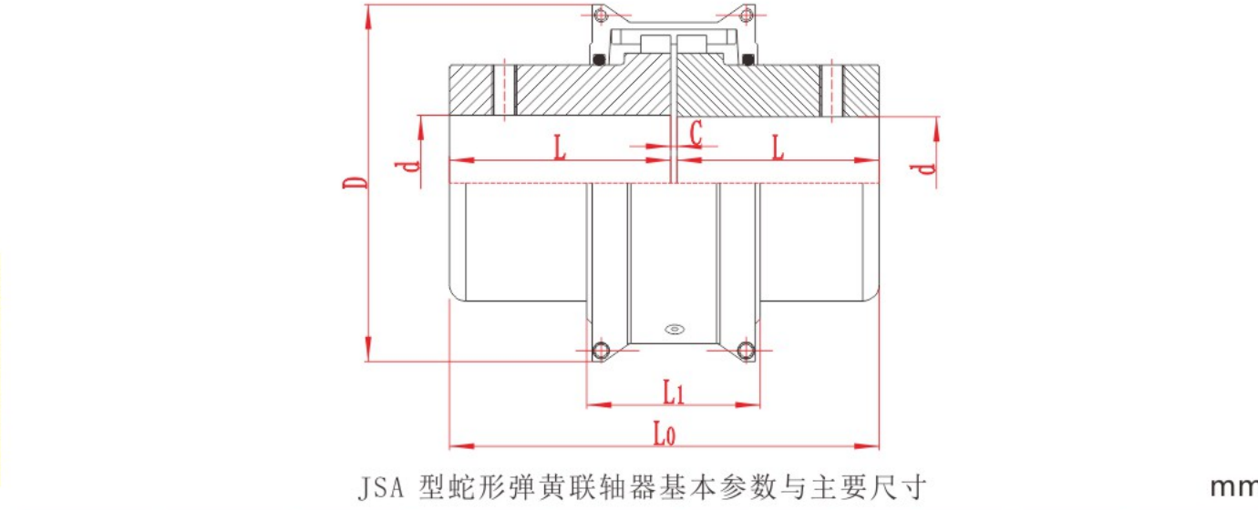
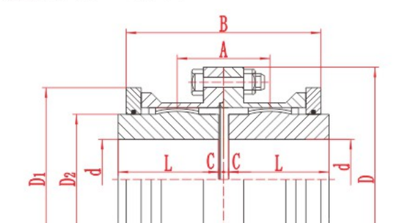
A conveyor that starts loaded and a mill drive that reverses can have similar running torque but very different peak histories. Send an annotated torque trace if available, or list the worst events and how often they occur. Add a shaft and guard drawing, operating speed range, lubricant access and any history of worn teeth, cracked grids or repeated failures. For a RONGXING DRIVE GICL or JSA candidate, ask for the exact size, bore arrangement and written acceptance of the stated duty. If a jam must trigger a controlled disconnect, specify a torque-limiting device and its trip requirement.