Technical Resources
Pin Bush Coupling Selection: Torque, Speed and Shaft Fit
Start pin bush coupling selection with the load and speed at the coupling, then check both shaft ends and the space around the assembly. A pin bush coupling transmits torque through pins and resilient bushes between its flanges. The pins, bushes and
Start pin bush coupling selection with the load and speed at the coupling, then check both shaft ends and the space around the assembly. A pin bush coupling transmits torque through pins and resilient bushes between its flanges. The pins, bushes and hubs must suit the same operating duty.
Can a pin bush coupling be selected by shaft diameter alone?
No. Shaft diameter tells you whether a catalogue bore is a candidate. The coupling also has to carry the running and peak loads at the required speed, fit both shaft ends and accommodate the movement expected in service. Even when two sizes accept the same bore, their ratings and installation dimensions can differ.
Check the duty before choosing the bore
Record the power transmitted at the coupling in kW and the speed at that shaft in r/min. Note the speed range, starting load and any shocks or reversals.
Screen sizes against torque and speed for the actual duty. Use the series supplier’s selection method and any application factor it specifies. Compare known peak loads against the applicable peak limit.
Check both hubs separately. Provide each shaft diameter, fit, keyway and usable engagement length. Match the bore form and length to the drawing for the exact size.
Check the shaft spacing, guard clearance and space for removing pins and bushes. Confirm the selected assembly’s limits for alignment, movement and the bush material’s service environment.
Example using running power and speed
If a coupling transmits 15 kW at 1,450 r/min in steady operation, the running torque is approximately 99 N·m. Use T ≈ 9,550 × P / n, where T is in N·m, P is the transmitted power in kW and n is coupling speed in r/min. This example gives steady running torque. The selection still needs the starting load and the series-specific duty check.
Read the TL drawing with the model table
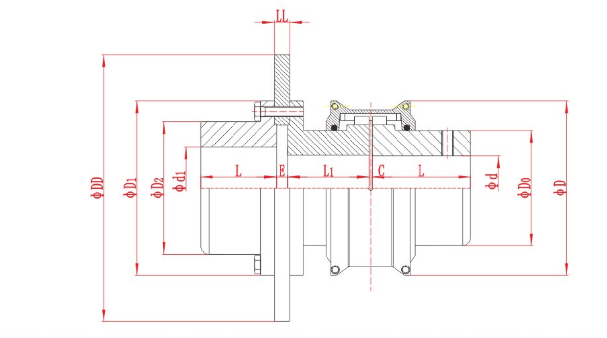
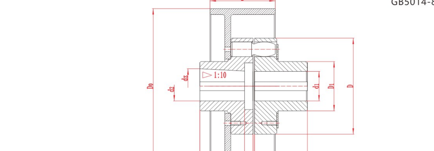
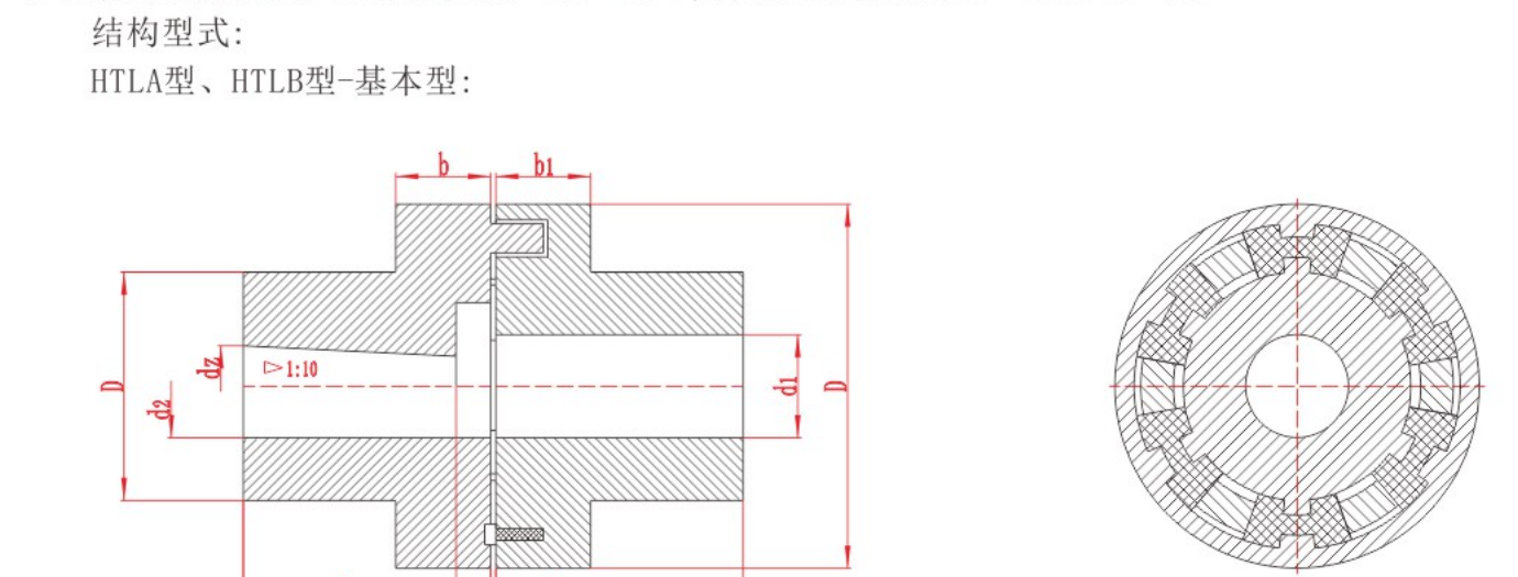
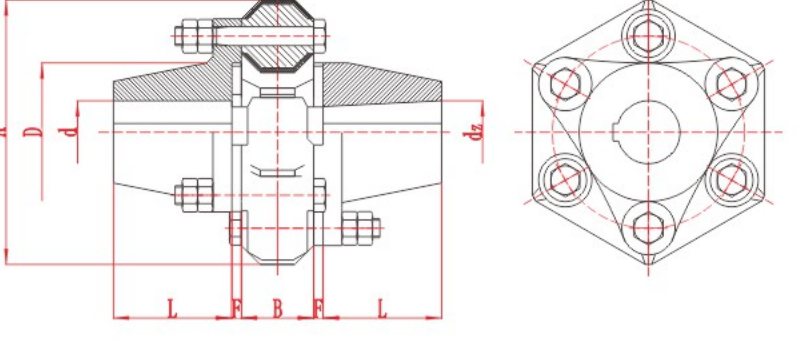
The RONGXING DRIVE TL Flexible Sleeve Pin Coupling table lists nominal torque, permissible speed and bore and length arrangements. Use the same model row and approved drawing for both shaft ends. When replacing an existing coupling, compare the old and proposed drawings, including the shaft-end spacing and the pin and bush interfaces.

For an industrial drive in India, send the equipment drawings, duty data and existing coupling identification with your selection enquiry. State whether you need a complete assembly or replacement pins and bushes.