
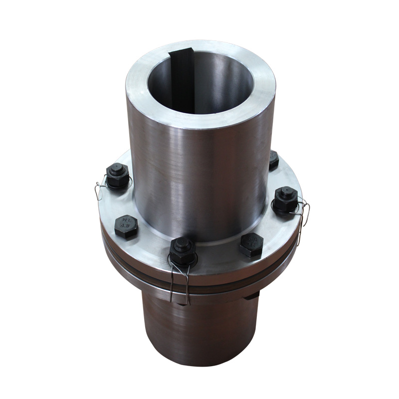
JZM Diaphragm Coupling for Heavy Machinery
JZM Diaphragm Coupling for Heavy Machinery with technical data and assembly drawing for preliminary selection.
View JZM Diaphragm Coupling for Heavy Machinery DetailsCurated technical topic
A disc coupling transmits torque between two shafts through a pack of thin metal discs. The discs flex to accommodate limited shaft movement while resisting torsional twist. Single-flex and double-flex arrangements handle different shaft offsets, so selection starts with the assembly layout. Compare RONGXING DRIVE JZM and JZMJ models using their published drawings and technical tables. For a flexible disc coupling, check operating torque, speed, both shaft bores and the installed shaft-end spacing together. Final suitability depends on the selected model, duty cycle and permitted movement.
These products retain their published Diaphragm Coupling names. Their drawings show the metallic flexible elements and shaft arrangements to review for disc-pack selection.
The JZM drawing shows one metallic disc-pack plane between the hubs. Review its compact arrangement, shaft connections and model-specific torque and speed data.
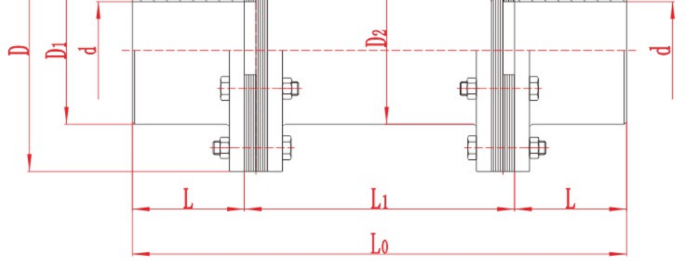
The JZMJ drawing shows two metallic disc-pack planes separated by a centre member. Review the shaft span, installed dimensions and rotating mass with the selected model.
| Selection point | Single-flex layout | Double-flex layout |
|---|---|---|
| Flexible planes | One disc-pack plane | Two separated disc-pack planes |
| Shaft movement | Normally angular and limited axial movement | Can also accommodate parallel offset through the two flexible planes |
| Installation review | Shaft alignment, hub positions and available space | Shaft-end spacing, flexible-plane separation and centre-member clearance |
| Drawing to review | JZM model drawing | JZMJ model drawing |
Permitted angular, axial and parallel movements are model-specific and interact under load. A single disc pack should not be selected to compensate for parallel offset on its own. Use the approved limits for the complete assembly.

Start with operating torque and speed, then check peak loads, starts, stops and reversals. Confirm that both shaft bores, hub connections and the installation envelope suit the same model. Published series maxima describe different sizes and should not be combined into a single operating specification.
Measure the distance between shaft ends, commonly called DBSE, at the intended installation position. For a centre-member arrangement, confirm the overall length and space required for assembly or removal. Use the drawing to interpret L, L1, L0 and S; a catalogue length field is not automatically the installed DBSE.
Provide expected angular, axial and parallel movement, temperature and environmental conditions. Balance requirements and the effect of a longer rotating member need review for the proposed operating speed. Disc-pack flexibility does not replace shaft alignment or a torsional assessment where the drive requires one.
Disc coupling and disk coupling commonly describe the same industrial construction. Disc type coupling, disc pack coupling and flexible disc coupling emphasise its structure or flexible element. A metal disc coupling uses metal flexure; the name alone does not establish material grade, backlash, torque capacity or speed capability.
Flexible membrane coupling and flexible plate coupling can describe a wider range of designs. Identify the actual torque path, attachment pattern and number of flexible planes before treating those terms as equivalent to a laminated disc-pack assembly. Compare the product drawing and specification when replacing an existing coupling.
The metallic flexible element generally requires no lubrication. Inspection still matters: follow the assembly instructions for checking disc condition, fasteners, alignment and signs of abnormal loading. Review the operating cause before replacing a damaged pack.
For a replacement enquiry, provide the complete coupling designation, assembly drawing and disc-pack details. Confirm the bolt pattern, geometry, thickness, material and specified hardware. Parts that look similar may have different load capacity or movement limits.
Compare the relevant JZM or JZMJ model row with the assembly drawing. Confirm the final dimensions, materials and operating suitability with RONGXING DRIVE before ordering.
JZM Diaphragm Coupling for Heavy Machinery with technical data and assembly drawing for preliminary selection.
View JZM Diaphragm Coupling for Heavy Machinery Details
JZMJ Diaphragm Coupling for Heavy Machinery with technical data and assembly drawing for preliminary selection.
View JZMJ Diaphragm Coupling for Heavy Machinery Details
Identify angular, parallel and axial misalignment. Learn how to measure each one and check the installation tolerance for a flexible coupling.
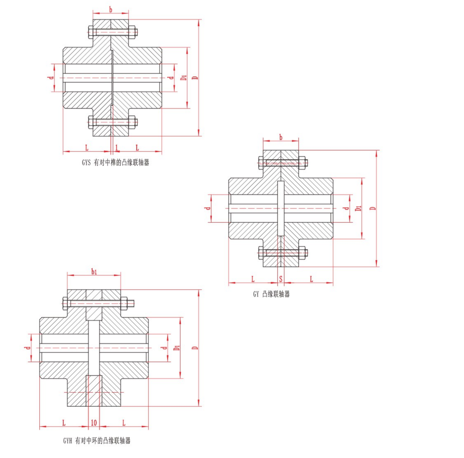
The two main types of mechanical shaft coupling are rigid and flexible. A rigid coupling joins shafts without a flexible element and depends on the required alignment being maintained. A flexible coupling accommodates limited movement within the limi
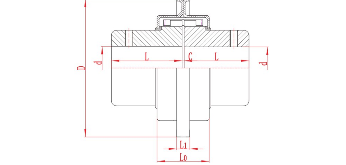
The main types of pump shaft couplings are rigid couplings and flexible designs such as jaw, tyre, grid, gear and disc or diaphragm couplings. For a centrifugal pump with separate driver and pump shafts, start with the pump layout. The space needed t
Topic FAQ
A disc coupling connects two shafts through a flexible metal disc pack. Torque passes through alternating bolted connections, while the thin discs bend to accommodate the movement allowed by the selected design.
Disc and disk are spelling variants when they describe the same industrial metal disc-pack construction. Check the drawing when a supplier uses coupling disk: the term can also describe an individual component or a different flexible element.
A disc pack coupling uses a stack of thin metal discs as its flexible element. The complete assembly also includes hubs, fasteners and, in some configurations, an intermediate member. A replacement disc pack is only one part of the assembly.
A single-flex design has one flexible disc-pack plane and normally accommodates angular and limited axial movement. A double-flex design has two separated flexible planes and can also accommodate parallel shaft offset. Permitted movements and their combined limits depend on the model.
Membrane coupling is a broader family term. Disc-pack and diaphragm constructions can transmit torque through different attachment arrangements. RONGXING DRIVE lists JZM and JZMJ under their existing Diaphragm Coupling product names; compare their drawings and model data when specifying an industrial disc coupling.
The metal disc pack generally needs no lubrication because flexibility comes from elastic bending. Inspect the coupling as required by its instructions, including disc condition, fasteners and alignment. No lubrication does not mean that inspection can be omitted.
Provide power or operating torque, speed, peak loads, duty cycle, both shaft diameters and keyways, distance between shaft ends, expected misalignment and operating conditions. Include an existing assembly drawing and any balance, inspection or documentation requirements.
Outside diameter is insufficient. Confirm the coupling model, bolt circle, hole arrangement, disc geometry, pack thickness, material and fastener specification. The replacement must suit the complete assembly and duty; similar dimensions do not establish interchangeability.
Send torque, speed, shaft and installation data for a preliminary review.