Technical Resources
Coupling Alignment: Misalignment Types and Tolerances
Identify angular, parallel and axial misalignment. Learn how to measure each one and check the installation tolerance for a flexible coupling.
Coupling alignment positions the driver and driven shafts so their rotational centrelines come within the machine train’s specified limits in service. Measure offset and angularity in both the vertical and horizontal planes. Check axial spacing separately against the coupling drawing. For a flexible coupling, use the approved installation targets for the train and confirm the coupling’s capacity for the movement expected during operation.
What are the types of coupling misalignment?
| Type | What it describes | What to record |
|---|---|---|
| Angular | The shaft centre lines point in different directions. | Vertical and horizontal slopes, usually in mm per 100 mm or in degrees. Record the unit and method. |
| Parallel (radial) offset | The shaft centrelines are displaced sideways at the specified reference plane. Offset and angularity can occur together. | Vertical and horizontal offset in mm. Identify the plane used to report it. |
| Axial spacing or movement | The distance between two specified faces along the shaft axis, or a change in that distance during operation. | The installed gap in mm, the two faces used, and the expected axial travel or end float where applicable. |
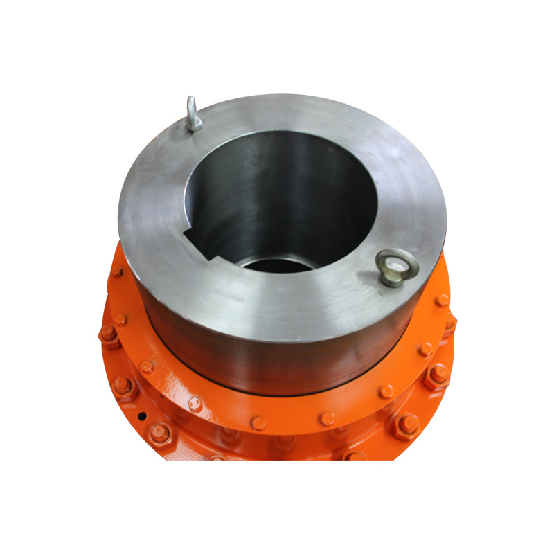
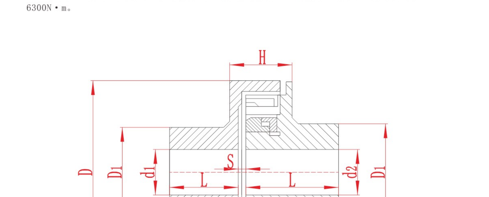
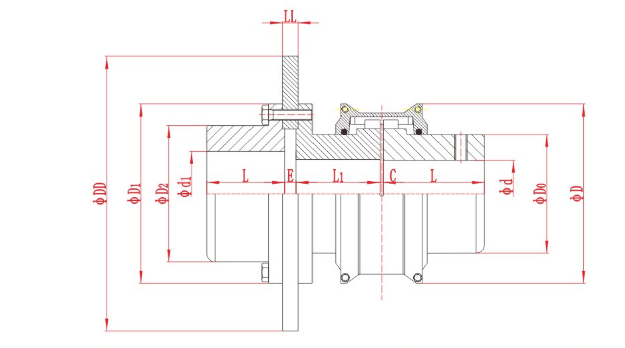
Keep the measuring reference with each reading. A shaft-end distance can differ from the hub-face gap if either hub is recessed or projects beyond its shaft end. For the drawing references used on a crowned gear coupling, see the gear coupling gap and alignment guide.
How do you measure coupling angular misalignment?
Use the shaft-alignment method specified for the machine train, such as laser alignment or a dial-indicator method. If the approved procedure uses face-gap readings, take them at opposite points on the same measuring circle. Record the distance between those points and follow the procedure for checking or compensating for face runout. Measure offset independently. For pump installations, see the Hydraulic Institute pump FAQs for dial-indicator and cold-alignment considerations.
For example, suppose the top and bottom gaps differ by 0.20 mm across a 100 mm measuring diameter. For ideal flat faces and small angles, the angularity in that plane is 0.20 mm per 100 mm. The angle in degrees is approximately arctan(0.20 ÷ 100) × 180 ÷ π, or 0.115°. Use the actual measuring diameter in the calculation and compare the result with the approved limit in the same unit. A reading in mm per 100 mm describes slope. A reading in mm at the coupling plane describes offset.
Which flexible coupling alignment tolerance applies?
For acceptance, check the coupling installation instructions and the driver and driven equipment requirements for the exact train. Compare limits only after matching units, reference planes and measurement conditions. For a motor and pump that move as they warm up, the approved cold target may call for a deliberate offset. Resolve conflicting targets with the responsible equipment suppliers before commissioning. See the shaft alignment tolerance guide.
For selection, check the coupling’s allowable movement for the exact series and size. Ask the supplier whether the angular, radial and axial limits apply separately and what combination is allowed at your speed, load and duty. Use the expected movements together when asking for confirmation, including any axial travel or end float.

Use the XL model table and assembly drawing to identify the coupling size and dimensions. Request the approved installation limits for that size if your documents give catalogue dimensions only.
What should the alignment report include?
Identify the driver, driven equipment, coupling series and size, and applicable document revisions.
Record the method, reference plane, vertical and horizontal angle and offset, plus the axial spacing and its two reference faces.
Record whether the readings were taken cold or at operating condition, along with any approved thermal target. Check soft foot and external strain as specified by the equipment procedure.
Retake the readings after tightening the hold-down bolts to the specified torque. Keep the final readings alongside the applicable limits, with the source of each limit.
For help checking a coupling for your drive, share the series and size or an assembly drawing, both shaft diameters and end details, operating speed, nominal and peak torque, and the expected angular, radial and axial movement. Include the temperature conditions, duty cycle and any available alignment report.