Technical Resources
Types of Pump Couplings: How to Choose for a Centrifugal Pump
The main types of pump shaft couplings are rigid couplings and flexible designs such as jaw, tyre, grid, gear and disc or diaphragm couplings. For a centrifugal pump with separate driver and pump shafts, start with the pump layout. The space needed t
The main types of pump shaft couplings are rigid couplings and flexible designs such as jaw, tyre, grid, gear and disc or diaphragm couplings. For a centrifugal pump with separate driver and pump shafts, start with the pump layout. The space needed to remove the seal or bearing assembly can determine whether you need a removable spacer.
Common types of pump couplings
| Type | How it transmits torque | When to consider it | What to check |
|---|---|---|---|
| Rigid flange or split clamp | Rigid shaft joint | Pump assemblies that specify a rigid connection | OEM alignment, shaft position and, where applicable, impeller setting |
| Jaw or elastomeric sleeve | Polymer insert or sleeve | General-purpose duties within the selected element’s rating | Element material, temperature, chemical exposure and access |
| Tyre | Flexible elastomeric tyre | Duties that call for torsional compliance | Torque and speed, guard clearance and space to remove the element |
| Grid | Metal spring grid | Drives with shock loads where a resilient metal grid suits the duty | Lubrication, cover access and duty limits |
| Gear | Meshing metal teeth | Drives where torque and available diameter favour a gear coupling | Lubrication, seals, bore capacity and allowable movement |
| Disc or diaphragm | Flexing metal discs or diaphragms | Drives that call for a torsionally stiff flexing element without lubrication | Alignment, axial movement, speed and balancing requirements |
A spacer describes the assembly layout. Flexible spacer couplings can use different torque-transmitting elements, so check the specific assembly drawing when comparing quotations. The Hydraulic Institute’s flexible coupling guide covers coupling types and the information needed for selection.
Start with the pump layout
On a close-coupled pump with the impeller on the motor shaft or its extension, there may be no separate coupling to select. A split-coupled pump can have a pump-specific removable joint. Identify that joint on the OEM parts drawing and check any requirements for shaft position or impeller setting.
A frame-mounted centrifugal pump has separate pump and driver shafts. On a back pull-out pump, a removable spacer can leave enough space to withdraw the seal or rotating assembly while the casing and driver stay in place, if the pump layout allows it. Measure the distance between shaft ends (DBSE) from one shaft end face to the other. Check the spacer dimensions, removal direction and space needed to withdraw the parts on the pump and coupling drawings.
Check the duty, alignment and maintenance access
Record both shaft diameters, shaft extensions, fits and keyways. Add the transmitted power in kW at the coupling, operating speed in r/min and any known starting or peak load. For a variable-speed drive, include the speed range and any unusual starts or stops.
Check torque, speed, shaft fit and the installation envelope for the same proposed coupling size. Include expected thermal movement and follow the pump and driver manufacturers’ limits. A flexible coupling accommodates limited movement in service. Align the shafts to the installation requirements for the machine and coupling. The Hydraulic Institute’s pump FAQs describe laser and dial-indicator methods for checking alignment.
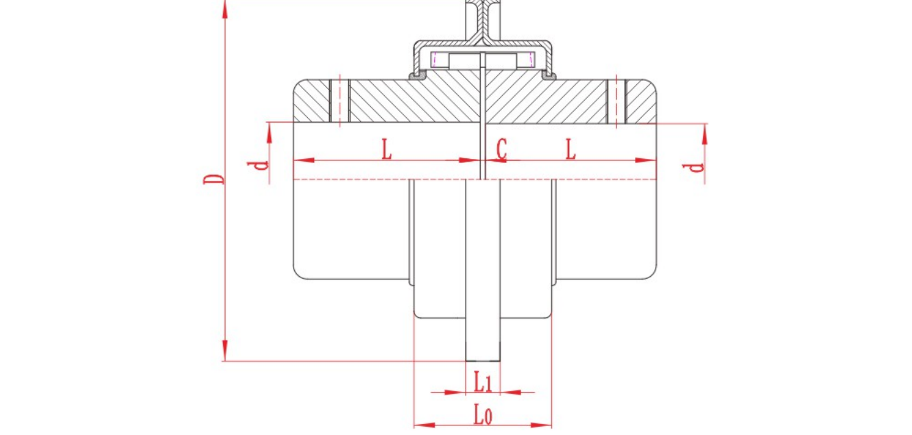
For a grid design, the RONGXING DRIVE JSB grid coupling drawing shows the cover and shaft interfaces to review. The JZMJ diaphragm coupling is an example of a metallic flexing-element design. Review the proposed drawing for either type against the pump duty and the space needed for service.
What to send for a replacement enquiry
If you are replacing a coupling on a process or water-service pump in India, send the pump model, existing coupling drawing or nameplate, both shaft-end dimensions and the DBSE. Include the operating duty, a photo of the guard and baseplate area, and any project specification that governs the replacement. If the project specifies an approved coupling, confirm the permitted configuration with the pump OEM.
When you request a coupling review, state whether the seal or rotating assembly must come out without moving the motor. Include the pump drawing that shows the removal path.