Technical Resources
Jaw Coupling Types: Straight, Curved, Wrap and Spacer Designs
Jaw couplings transmit torque through an elastomer between two metal hubs. Common descriptions include straight-jaw and curved-jaw profiles, solid and wrap-style spiders, and close-coupled or spacer assemblies. Each describes a different part of the
Jaw couplings transmit torque through an elastomer between two metal hubs. Common descriptions include straight-jaw and curved-jaw profiles, solid and wrap-style spiders, and close-coupled or spacer assemblies. Each describes a different part of the selection. A curved-jaw profile, for example, tells you about the hub and insert geometry. To learn how the insert comes out, check the assembly drawing.
What each jaw coupling type describes
| Type or option | What it describes | What to check |
|---|---|---|
| Straight or curved jaw | Hub and spider geometry | Check the exact series, profile, lobe count and drawing. Compare backlash only for the assembled design. |
| Solid spider or radially removable wrap | How the elastomer comes out | Check whether there is axial room to separate the hubs or radial room to remove the element and its retainer. |
| Close-coupled or spacer style | Distance and access between machines | Confirm the distance between shaft ends, the coupling drawing and the removal path. |
| Keyed, clamp or other hub attachment | How each hub grips its shaft | Check both bores, keyways or clamp details, usable engagement length and tool access. |
The Hydraulic Institute’s pump coupling guidebook treats close-coupled jaw, spacer-style jaw and wrap assemblies separately in its installation sections. Use the instructions for the actual assembly when planning service access.
Straight and curved jaws
In both profiles, the hub jaws engage a matching spider. The straight and curved descriptions refer to the geometry of that interface. Two spiders can have the same outside diameter and still differ in lobe shape, width or hub fit. When replacing an insert, identify the coupling series and size, then compare the spider profile and material grade against the manufacturer's drawing or part number.
For a reversing drive, ask how the specified hub and spider combination controls backlash. Any low-backlash claim applies to a particular assembly and fit. Check torsional stiffness, the permitted torque and speed, and how the element behaves at the service temperature. Use the supplier’s material rating if the coupling is exposed to oil, chemicals or heat.
Solid spider, wrap or spacer
A one-piece spider normally fits between the two hubs. Replacing it can require axial separation. A wrap-style element can be removed radially on an assembly designed for that procedure. Check room for the retainer and tools, and follow the coupling instructions. If a pump seal or another component must be withdrawn, confirm whether a removable spacer and the available shaft separation leave a clear removal path.
Before changing the coupling design, record the distance between shaft ends and both hub positions. A spacer can change the installed length and the room needed inside the guard.
How to compare the drawings
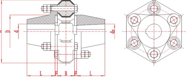
The RONGXING DRIVE XL Star Elastomer Coupling is a compact jaw-and-spider example. Check the element, shaft bores and overall envelope on its own drawing. The DL Multi-Jaw Coupling is a separate series. Its drawing and table call out jaw dimensions and screw quantity, which are useful when checking mounting and tool access. Use the drawing for the series you intend to order.
What to include in a jaw coupling enquiry
For a replacement on a pump, fan or other industrial drive in India, send the existing model or drawing and say whether you need the insert alone or the full coupling. Include both shaft diameters, fit and keyway details, operating speed in r/min, continuous and peak torque where known, shaft separation and clearance around the guard. If the duty involves frequent starts or reversals, include those conditions.
When you request a coupling review, add a clear photo of the hubs and element, plus the available service space. A marked-up sketch can show whether the element must come out without moving either machine.