
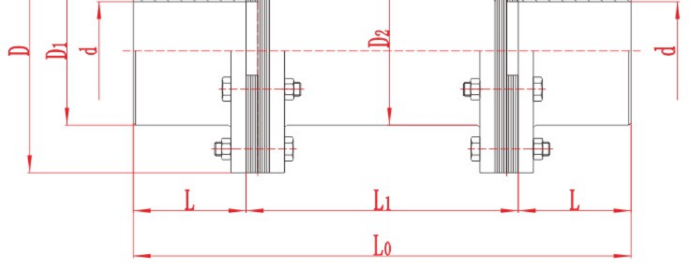
JZMJ Diaphragm Coupling for Heavy Machinery
JZMJ Diaphragm Coupling for Heavy Machinery with technical data and assembly drawing for preliminary selection.
View JZMJ Diaphragm Coupling for Heavy Machinery DetailsCurated technical topic
A spacer coupling transmits torque between two shafts through a centre section that spans the gap between their ends. On a pump drive, a removable spacer can provide clearance for seal or pump maintenance when the equipment layout allows it. On a longer drive span, the centre section bridges the distance between the machines. For a flexible spacer coupling, check the distance between shaft ends (DBSE), both shaft bores, operating torque and speed against the assembly drawing for the selected model.
For pump service, check the direction and clearance needed to remove the centre assembly and access the seal. For a longer shaft span, confirm the operating speed and any support requirements with the manufacturer. Measure DBSE between the two installed shaft end faces and use the assembly drawing to confirm the spacer and overall dimensions. For model selection, provide both shaft diameters and keyways, the installed DBSE, operating speed, power or torque, and an existing drawing if available.
JZMJ Diaphragm Coupling for Heavy Machinery with technical data and assembly drawing for preliminary selection.
View JZMJ Diaphragm Coupling for Heavy Machinery Details
ZLZ Intermediate-Shaft Flexible Pin Gear Coupling with technical data and assembly drawing for preliminary selection.
View ZLZ Intermediate-Shaft Flexible Pin Gear Coupling Details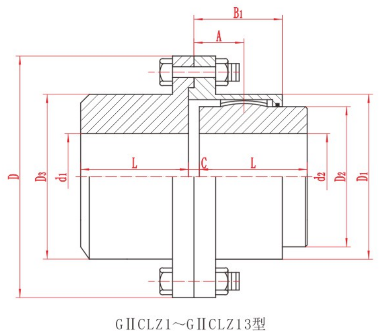
GIICLZ Crowned Gear Coupling with technical data and assembly drawing for preliminary selection.
View GIICLZ Crowned Gear Coupling Details
WGT Crowned Gear Coupling with Intermediate Sleeve with technical data and assembly drawing for preliminary selection.
View WGT Crowned Gear Coupling with Intermediate Sleeve Details
Identify angular, parallel and axial misalignment. Learn how to measure each one and check the installation tolerance for a flexible coupling.
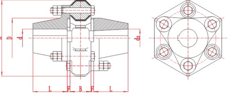
Jaw couplings transmit torque through an elastomer between two metal hubs. Common descriptions include straight-jaw and curved-jaw profiles, solid and wrap-style spiders, and close-coupled or spacer assemblies. Each describes a different part of the
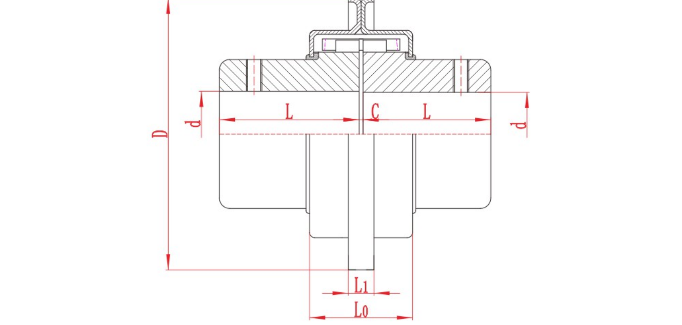
The main types of pump shaft couplings are rigid couplings and flexible designs such as jaw, tyre, grid, gear and disc or diaphragm couplings. For a centrifugal pump with separate driver and pump shafts, start with the pump layout. The space needed t
Topic FAQ
A spacer coupling transmits torque across the gap between two shaft ends. Depending on the design, its centre section can bridge a longer span or be removed to provide access for servicing the driven equipment.
It is a coupling with a centre spacer and flexible elements or gear meshes that accommodate specified shaft movement. Check the manufacturer's limits for angular, parallel and axial movement for the selected size and arrangement.
DBSE stands for distance between shaft ends. It is the axial distance between the two shaft end faces in the installed position. Use the assembly drawing to relate that distance to the spacer length and the overall coupling length.
Yes, if the centre assembly can be removed and the pump layout leaves enough space to withdraw the seal or service assembly. Check the removal direction and required clearance in the pump manufacturer's drawings or service instructions.
A matching DBSE is one fit check. Also verify both bores, keyways, hub engagement, torque, operating speed, allowable shaft movement and the space needed to remove the centre assembly.
Send the installed DBSE, both shaft diameters and usable shaft lengths, keyway dimensions, and the existing coupling drawing or nameplate if available. Include operating speed and motor power or torque so the replacement can be checked for fit and duty.
Send torque, speed, shaft and installation data for a preliminary review.