Technical Resources
Pin Bush Coupling Size Chart, Dimensions and Drawings
Compare TL and TLL pin bush coupling dimensions and drawings, with 22 model rows and an English PDF catalogue for preliminary selection.
This pin bush coupling size chart covers RONGXING DRIVE TL and TLL flexible sleeve pin couplings. Compare the model-specific torque, permissible speed, shaft bores and installation dimensions with the corresponding drawing. TL uses the sleeve-pin layout; TLL adds a brake drum. All dimensions are in mm unless another unit is stated. The English PDF catalogue contains the same two series for preliminary comparison.
Download the English TL/TLL pin bush coupling catalogue PDF (3 pages, revision 21 November 2026).
Choose the series before comparing dimensions
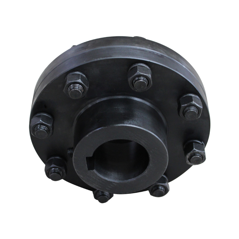
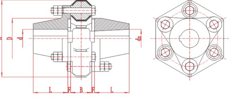
A pin and bush coupling can have different pin, sleeve and flange arrangements. Use the TL Flexible Sleeve Pin Coupling drawing for the basic sleeve-pin layout and the TLL Flexible Sleeve Pin Coupling with Brake Drum drawing for the brake-drum variant.
Other elastic pin designs require their own model tables. A similar bore or outside diameter does not establish that pins, bushes or complete assemblies can be interchanged.
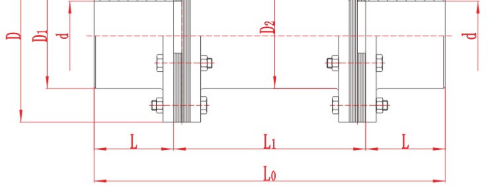
TL pin bush coupling drawing and size chart
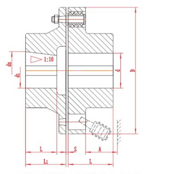
Tn is nominal torque in N·m; [n] is permissible speed in r/min. Bore diameters and lengths, D, S and A are in mm. Mass is in kg.
| Model | Tn (N·m) | [n] (r/min) | Bore d / d₁ / d₂ (mm) | Bore length L₁ (mm) | Bore length L (mm) | D (mm) | S (mm) | A (mm) | Mass (kg) |
|---|---|---|---|---|---|---|---|---|---|
| TL1 | 6.3 | 8800 | 9~14 | 20~32 | 14~20 | 71 | 3 | 18 | 1.2 |
| TL2 | 16 | 7600 | 12~19 | 32~42 | 20~42 | 80 | 3 | 18 | 1.8 |
| TL3 | 31.5 | 6300 | 16~25 | 42~62 | 30~62 | 95 | 4 | 35 | 2.0 |
| TL4 | 63 | 5700 | 20~32 | 52~82 | 38~82 | 106 | 4 | 35 | 2.4 |
| TL5 | 125 | 4600 | 25~40 | 62~112 | 44~112 | 130 | 5 | 45 | 8.5 |
| TL6 | 250 | 3800 | 32~50 | 82~112 | 60~112 | 160 | 5 | 45 | 11 |
| TL7 | 500 | 3600 | 40~65 | 112~142 | 84~142 | 190 | 5 | 45 | 16 |
| TL8 | 710 | 3000 | 45~80 | 112~172 | 84~172 | 224 | 6 | 65 | 26 |
| TL9 | 1000 | 2850 | 50~85 | 112~172 | 84~172 | 250 | 6 | 65 | 32 |
| TL10 | 2000 | 2300 | 63~120 | 142~212 | 107~212 | 315 | 8 | 80 | 68 |
| TL11 | 4000 | 1800 | 80~140 | 172~252 | 132~252 | 400 | 10 | 100 | 125 |
| TL12 | 8000 | 1450 | 100~180 | 212~302 | 167~302 | 475 | 12 | 130 | 220 |
| TL13 | 16000 | 1150 | 120~220 | 212~352 | 167~352 | 600 | 14 | 180 | 430 |
The source groups TL bore lengths under Y/J/J₁/Z and gives separate L₁ and L columns. Confirm the shaft and bore form with the drawing. The source note identifies Y/J₁/Z₁ arrangements and calls for a structural check for J/Z forms. Preserve the access dimension marked A when reviewing the surrounding equipment.
TLL pin bush coupling dimensions with brake drum
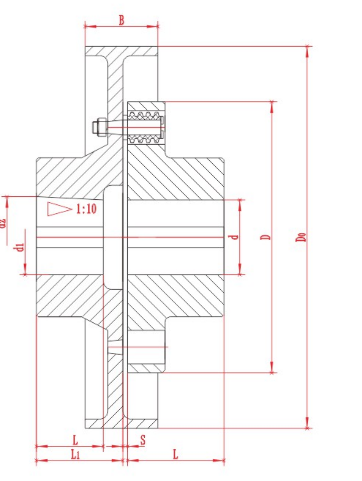
Use the TLL row for torque, speed, bore and installation comparison. Length L is listed for Y-type bores; L₁ is listed for J/Z-type bores. All dimensions below are in mm; mass is in kg.
| Model | Tn (N·m) | [n] (r/min) | Bore d / d₁ / d₂ (mm) | Y bore length L (mm) | J/Z bore length L₁ (mm) | D₀ (mm) | B (mm) | D (mm) | S (mm) | A (mm) | Mass (kg) |
|---|---|---|---|---|---|---|---|---|---|---|---|
| TLL1 | 125 | 3800 | 25~35 | 62~82 | 44~82 | 200 | 85 | 130 | 5 | 45 | 10 |
| TLL2 | 250 | 3000 | 32~42 | 82~112 | 60~112 | 250 | 105 | 160 | 5 | 45 | 16 |
| TLL3 | 500 | 2400 | 40~48 | 112 | 84~112 | 315 | 132 | 190 | 5 | 45 | 30 |
| TLL4 | 710 | 2400 | 45~63 | 112~142 | 84~142 | 315 | 132 | 224 | 6 | 65 | 40 |
| TLL5 | 1000 | 2400 | 50~71 | 112~142 | 84~142 | 315 | 168 | 250 | 6 | 65 | 48 |
| TLL6 | 2000 | 1900 | 63~95 | 142~172 | 107~172 | 400 | 168 | 315 | 8 | 80 | 94 |
| TLL7 | 4000 | 1500 | 80~110 | 172~212 | 132~212 | 500 | 210 | 400 | 10 | 100 | 130 |
| TLL8 | 8000 | 1200 | 100~130 | 212~252 | 167~252 | 630 | 265 | 475 | 12 | 130 | 310 |
| TLL9 | 16000 | 1000 | 120~170 | 212~302 | 167~302 | 710 | 298 | 600 | 14 | 180 | 580 |
How to read the coupling specification
Model: identifies a size within its own series. A size number is not the shaft diameter.
Tn and [n]: compare torque and permissible speed for the same row. Series maxima belong to different sizes and are not simultaneous operating ratings.
d, d₁ and d₂: refer to the bore arrangements shown. Confirm both shaft interfaces, keys and fits.
L and L₁: are drawing-specific bore lengths. Match the selected shaft form.
D, S and A: must be interpreted from the corresponding assembly drawing, including the access shown.
D₀ and B: describe the TLL brake-drum envelope.
These tables reproduce catalogue dimensions for preliminary comparison. Confirm the final model, dimensions, materials and operating suitability with RONGXING DRIVE before ordering, manufacture or installation.
Pin, bolt and bush replacement checks
The complete-coupling chart does not establish the pin thread, shoulder length, fastener grade or tightening torque. Use the approved pin and assembly drawings for those details. Do not infer a coupling bolt specification from shaft bore alone.
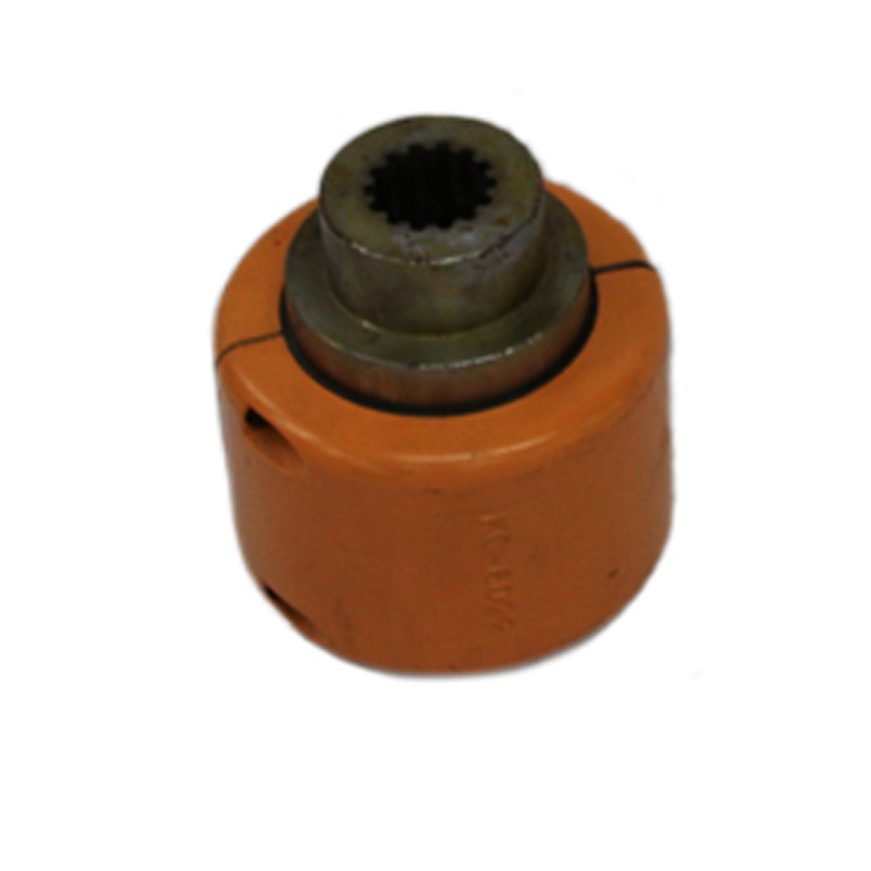
For a coupling rubber bush enquiry, provide the existing series and model, photographs or a parts drawing, inside diameter, outside diameter, length and profile. Confirm material grade and hardness for the actual duty. The dimensional catalogue does not specify a universal bush material, and a matching outside diameter does not prove replacement suitability.
Prepare the data for preliminary selection
Send operating torque or power, speed, peak loads and duty cycle, both shaft diameters and keyways, installed dimensions, maintenance access, expected shaft movement and operating conditions. Include the existing drawing where available.
For the next checks, see pin bush coupling selection and the pin bush coupling installation checklist.
Frequently asked questions
How do I find the correct pin bush coupling size?
Identify the series and compare operating torque, speed, both shaft bores, bore lengths and installation space. Then check the selected model against its drawing and duty. Shaft diameter alone is insufficient.
Are TL and TLL coupling dimensions interchangeable?
TL and TLL use different assembly layouts. TLL includes a brake drum and additional D0 and B dimensions. Compare the complete drawing and model row before replacing either series.
Where can I download a pin bush coupling size chart PDF?
The English TL/TLL PDF catalogue linked above contains both series, assembly drawings, 22 model rows and preliminary selection notes. Its revision date is 21 November 2026.
Does the size chart specify coupling bolt or pin threads?
The tables describe complete-coupling dimensions and ratings. They do not provide a pin-thread schedule. Confirm the pin thread, shoulder geometry, material and tightening requirements from the approved parts drawing.
Can I find the rubber bush size from the shaft bore?
A shaft-bore diameter does not define the bush dimensions. Record the coupling series, pin arrangement, bush inside and outside diameters, length and profile, then verify the replacement against the parts drawing.
Which rubber bush material should I specify?
Use the material grade and hardness approved for the exact coupling and duty. Temperature, fluids, load and movement affect the review. These TL/TLL dimensional tables do not establish a universal rubber or polyurethane specification.
Catalogue source and revision
TL and TLL tables and assembly drawings are based on the RONGXING DRIVE Chinese product catalogue, printed pages 46–47. English dimensional catalogue revision: 21 November 2026. Download the TL/TLL size chart PDF to keep the two series together for preliminary review.