Technical Resources
How do I choose between a pin bush coupling and a jaw coupling for an industrial pump?
For an industrial pump replacement, start with the pump maker’s coupling specification and the installed drawing. Compare a pin bush coupling when the pump already has a flanged pin-and-bush arrangement you want to retain. A jaw coupling is a candida
For an industrial pump replacement, start with the pump maker’s coupling specification and the installed drawing. Compare a pin bush coupling when the pump already has a flanged pin-and-bush arrangement you want to retain. A jaw coupling is a candidate where its hub-and-spider assembly fits the shafts, duty and service space. If the seal must come out with the motor in place, check the removal path before choosing either design.
Pin bush and jaw couplings compared
| Check | Pin bush coupling | Jaw coupling |
|---|---|---|
| Torque path | Pins and their resilient bushes transfer load between flanges. | The jaws on the hubs load a matching elastomer spider. |
| Existing pump fit | Check both shaft bores, keyways and the pin and bush arrangement against the original drawing. | Check both bores, keyways or clamps, the jaw profile and the exact spider. |
| Service access | Check how the pins and bushes withdraw and whether the guard or nearby equipment blocks access. | Check whether the design needs axial hub separation or allows radial element removal. |
| Duty and environment | Verify torque, speed, permitted movement and bush material for the size under review. | Verify the same duty limits and the spider grade for the selected size. |
| Seal removal | Confirm the available space on the pump drawing and whether the coupling arrangement leaves the required removal path. | If the pump needs a removable spacer, specify a compatible spacer assembly and verify the withdrawal path. |
Check the pump duty and shaft fit
Record the transmitted power at the coupling in kW, running speed in r/min, and the speed range if the pump uses a variable-speed drive. Include known peak torque, starting frequency and any reversals or shocks. Compare the proposed size against the supplier’s duty ratings, both shaft bores and keyways, and the installed envelope. Use the coupling maker’s application factors and the pump maker’s limits. For either design, check the elastomer’s suitability for the actual temperature and exposure to oil or process chemicals.
Check angular and parallel alignment and the expected axial movement in service. Both coupling types accommodate limited movement within the specified limits. Follow the pump and coupling installation tolerances. The Hydraulic Institute’s pump FAQs describe laser and dial-indicator methods for checking alignment.
Check how the wear parts and seal come out
Measure the distance between shaft ends from one shaft end face to the other. Mark that dimension, the available radial clearance and the guard position on the pump drawing. Then check the actual removal direction for the bushes or spider. Some jaw assemblies need axial room to separate the hubs. Radial replacement is available on designs made for it.
On a back pull-out pump, use the pump maker’s drawing to verify the space needed to remove the seal or rotating assembly. If the installed coupling has a removable spacer, carry that maintenance requirement into the enquiry. A different coupling may fit the shafts while leaving too little room to withdraw the seal.
Use the series drawings to compare the interfaces
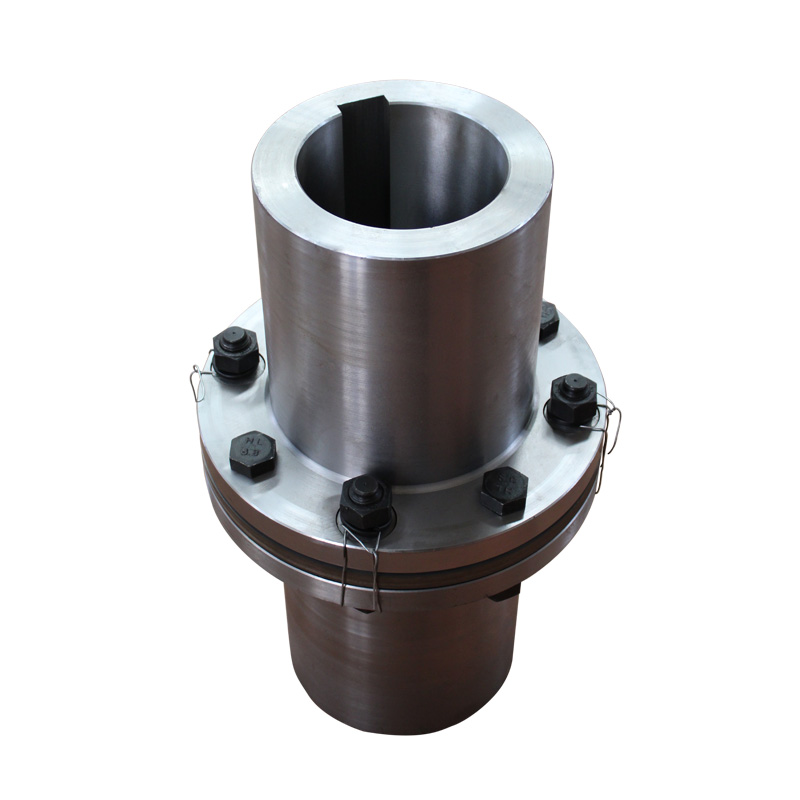
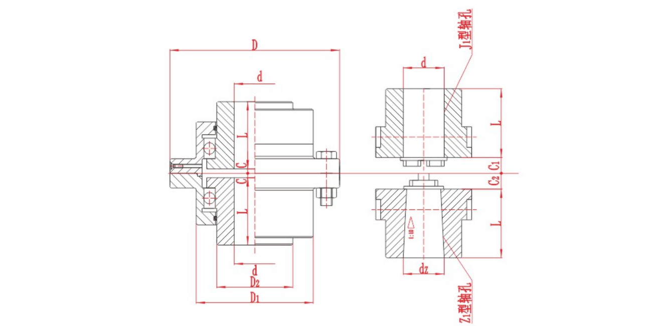
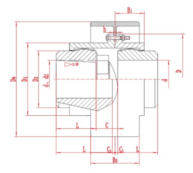
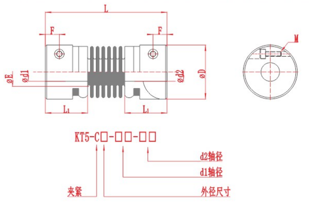
The RONGXING DRIVE TL Flexible Sleeve Pin Coupling is a sleeve-and-pin example. Check the selected bore arrangement and access to the pins and sleeves. For the XL Star Elastomer Coupling, check the shaft bores, spider and assembly length. Each drawing applies to its own series. For an existing pump, confirm interchangeability against the original and proposed drawings before ordering either complete assemblies or wear parts.


What to send with an Indian pump enquiry
For a coupling review, send the pump model, the installed coupling drawing or nameplate, dimensions for both shaft ends, the duty data and a photo of the guard and baseplate. Say whether you need bushes, a spider or a complete assembly. If either machine must stay in place during service, mark the required removal path on the drawing. Include any project requirement that controls the coupling or spare parts.