Technical Resources
Universal Joint Couplings: Types, Uses and How They Work
A universal joint coupling transmits rotation and torque between shafts that meet at an angle. In a cross-type joint, two fork-shaped yokes pivot on a four-armed cross. The joint can transmit torque while it articulates, but a single joint at a nonze
A universal joint coupling transmits rotation and torque between shafts that meet at an angle. In a cross-type joint, two fork-shaped yokes pivot on a four-armed cross. The joint can transmit torque while it articulates, but a single joint at a nonzero angle also makes the output speed rise and fall during each revolution, even when the motor speed is steady.
What do universal joint, U-joint and Cardan joint mean?
In a drivetrain, U-joint is short for universal joint. Cardan joint and Hooke joint usually refer to the cross-and-yoke design. A cross kit is a service component: confirm which bearing cups, seals and retainers come with it. A Cardan shaft is the complete shaft assembly, often with a joint at each end. On a purchase order, name the part you want. A supplier may read “universal cross joint coupling” as a request for a cross kit.
How does a cross-type universal joint work?
One yoke turns with the driving shaft and loads two opposite trunnions on the cross. The other pair of trunnions transfers the load to the driven yoke. Bearings at the trunnions let the yokes pivot as the joint rotates. At an angle, the geometry changes the instantaneous speed ratio twice per revolution. More articulation generally means a larger speed fluctuation for a single joint. At zero angle the ideal kinematic fluctuation disappears. Zero angle by itself does not establish an acceptable running condition for a specific bearing design.
For an illustration of this motion and the conditions for cancellation, see the Applied Mechanics chapter on shaft couplings.
Types of universal joint arrangements
| Arrangement | What it does | What to check |
|---|---|---|
| Single Cardan joint | Connects two intersecting shaft axes at one articulation point. | Check how much speed variation the driven machine can tolerate at the running angle. |
| Two separate Cardan joints | Uses an intermediate shaft. In a correctly phased coplanar layout with equal joint angles, the second joint can cancel the ideal speed variation from the first at the output. | Check both true operating angles and the specified yoke phase through the full travel of the machine. The intermediate shaft still varies in speed. |
| Centred double Cardan joint | Packages two closely spaced joints with a centring mechanism that makes them share the angle. With the required geometry, the output can run at constant speed relative to the input. | Check the centring mechanism, mounting space and ratings for the complete unit. |
Fixed length and telescopic describe the shaft assembly. Those terms tell you whether the shaft can change length. A single joint on its own provides angular articulation; axial travel requires a separate provision such as a slip spline.
Where are universal joint couplings used?
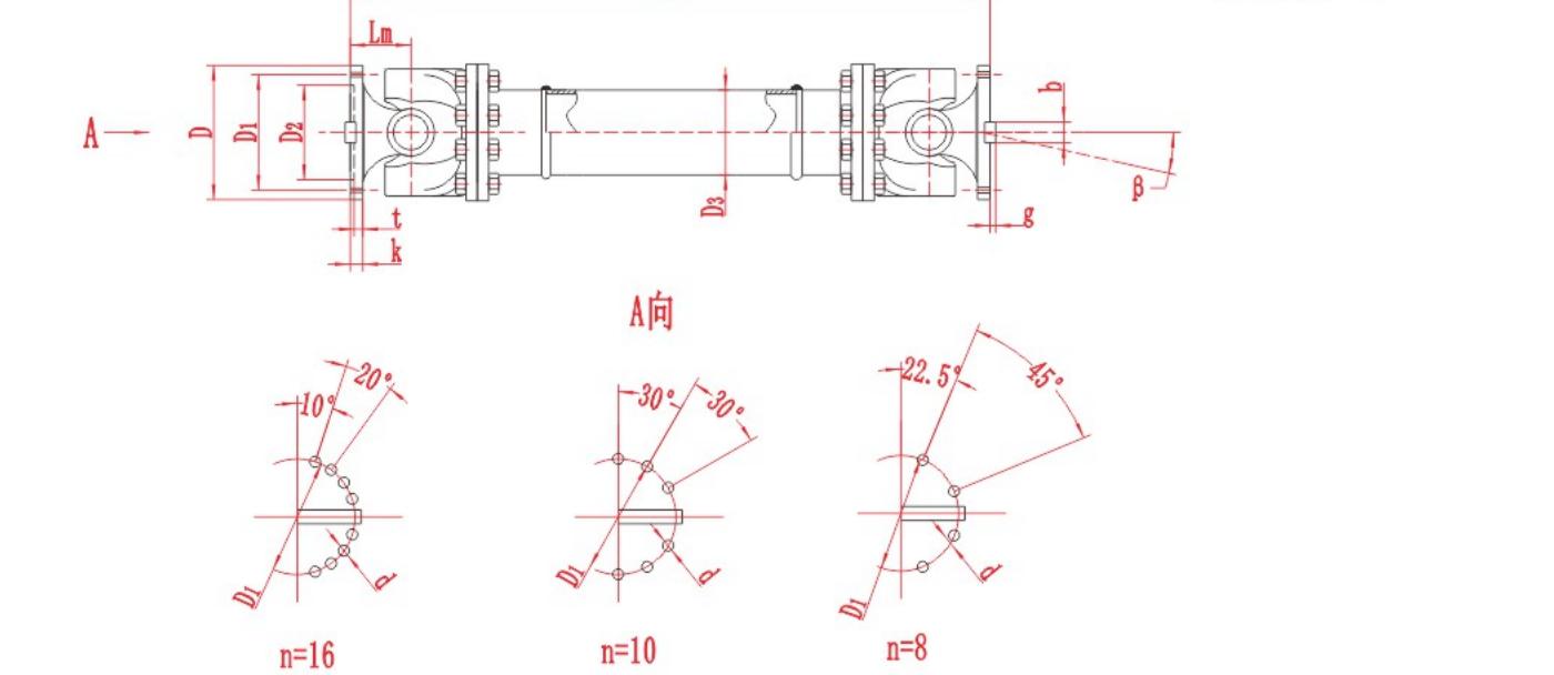
On a rolling mill, a jointed shaft can carry torque from a gearbox to a roll whose axis sits at an angle to the drive. A telescopic assembly may be appropriate if roll movement also changes the distance between the connections. On other process equipment, the same principle can link a reducer to a driven unit when the shaft axes cannot be aligned. Compact joints for instruments or vehicle steering use the same basic motion, but their dimensions and duty ratings tell you little about whether they will suit a mill drive.
Can a universal joint coupling connect an electric motor directly?
Yes, where the motor, driven machine and joint assembly are approved for the layout. Start with a sketch that shows both shaft axes, the support bearings and the working angles in each machine position. Check running and transient torque, the speed range, vibration sensitivity and any axial movement. Ask the motor and gearbox suppliers to confirm the allowable loads at their shafts. For a motor and pump that can be aligned within their specified tolerances, evaluate the flexible coupling recommended for that pump before introducing a universal joint.
Use the actual combination of torque, rpm and angle to check the model. Separate catalogue maxima do not tell you whether the shaft can run at those three limits together. See the combined operating limits guide for the data to review.
What to specify before ordering
Say whether you need a cross kit, one complete joint or a complete jointed shaft.
List running and transient torque in N·m, speed in rpm and the working angle at each joint in degrees.
For a complete shaft, give the installed length and movement range in mm, with the measurement datum marked. Attach drawings of both interfaces.
Describe the machine duty, including starts, reversals, shock loads and the operating environment.
For industrial drives that need a complete flanged assembly, see the Rongxing Cardan shaft range. Compare the model drawing and duty limits with your installation.