
JSB Grid Coupling
JSB Grid Coupling with technical data and assembly drawing for preliminary selection.
View JSB Grid Coupling DetailsCurated technical topic
JSB Grid Coupling with technical data and assembly drawing for preliminary selection.
View JSB Grid Coupling Details
LA Tire Coupling with technical data and assembly drawing for preliminary selection.
View LA Tire Coupling Details
LB Tire Coupling with technical data and assembly drawing for preliminary selection.
View LB Tire Coupling Details
TL Flexible Sleeve Pin Coupling with technical data and assembly drawing for preliminary selection.
View TL Flexible Sleeve Pin Coupling Details
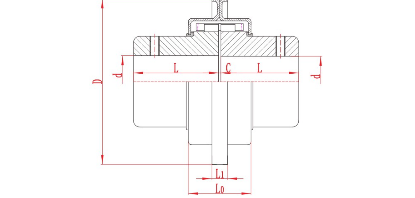
ZLZ Intermediate-Shaft Flexible Pin Gear Coupling with technical data and assembly drawing for preliminary selection.
View ZLZ Intermediate-Shaft Flexible Pin Gear Coupling Details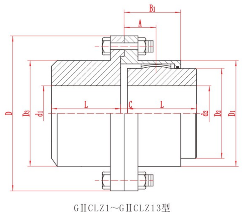
GIICLZ Crowned Gear Coupling with technical data and assembly drawing for preliminary selection.
View GIICLZ Crowned Gear Coupling Details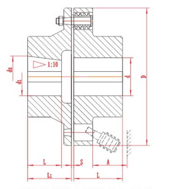
Compare TL and TLL pin bush coupling dimensions and drawings, with 22 model rows and an English PDF catalogue for preliminary selection.
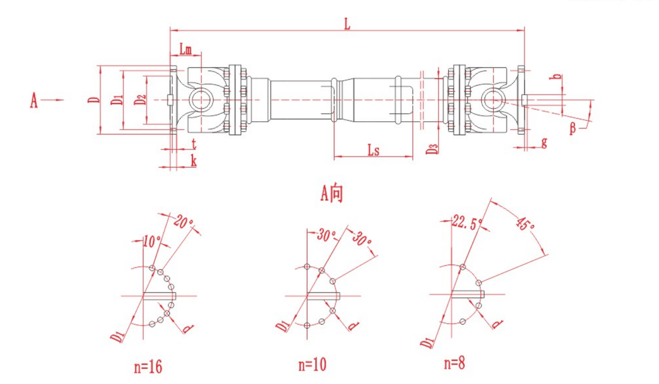
Use shaft-speed vibration data, joint-angle measurements and the approved drive tolerances to investigate vibration in an industrial Cardan shaft.
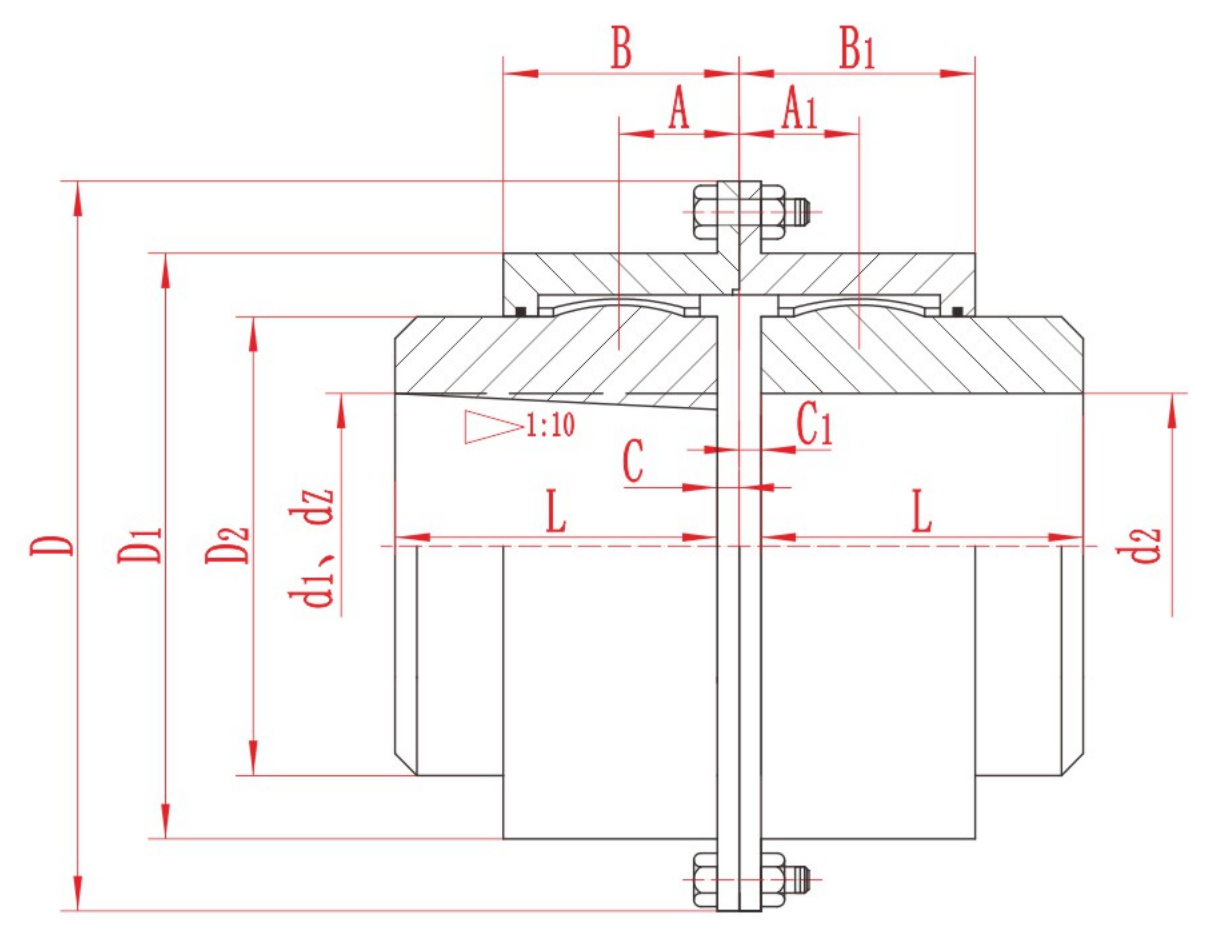
Before operating a gear coupling, confirm the approved lubricant, the fill quantity and units, the filling method and the next service interval for the exact model. Inspect the seals and plugs, then confirm whether the coupling was filled during asse

For a pin bush coupling installation, use the approved assembly drawing and instructions for the exact series and size. Confirm the hub fits, installed dimensions, alignment targets and fastener requirements before the drive is put back into service.

The main types of pump shaft couplings are rigid couplings and flexible designs such as jaw, tyre, grid, gear and disc or diaphragm couplings. For a centrifugal pump with separate driver and pump shafts, start with the pump layout. The space needed t
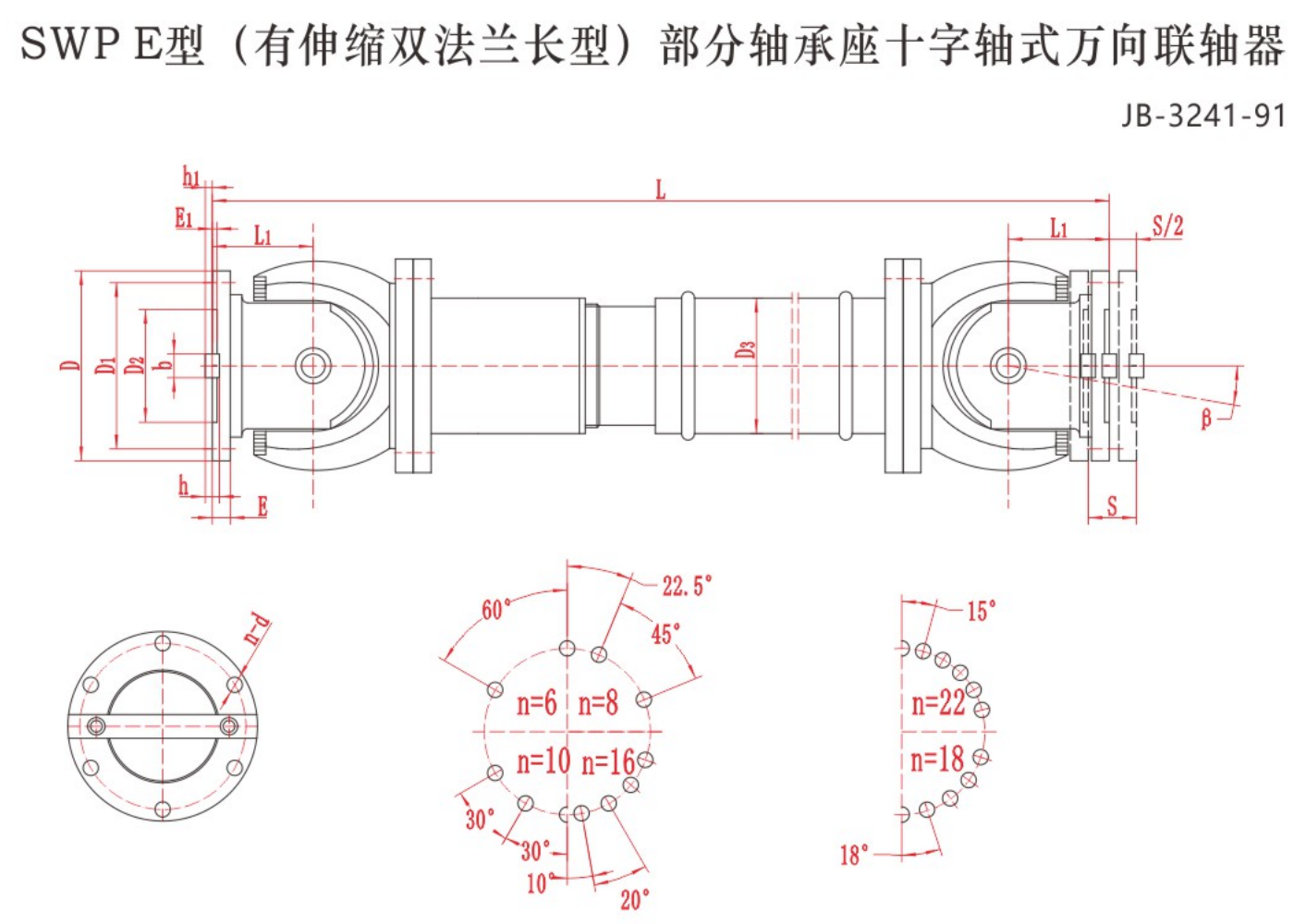
Before ordering an industrial cardan shaft, record both flange diameters, pilot fits, bolt circles, hole sizes and clocking. Use the drawing checklist.
Send torque, speed, shaft and installation data for a preliminary review.