Technical Resources
Which coupling structures should I compare for a high-torque rolling mill drive?
Compare gear, cardan shaft, grid and diaphragm designs for a high-torque rolling mill drive by connection position, operating duty and maintenance access.
Compare crowned gear couplings, universal-joint cardan shafts, grid couplings and metallic disc or diaphragm couplings for a high-torque rolling mill drive. Start with the connection you are sizing. The motor-to-gearbox connection may run at a different speed and see different peaks and shaft movement from the gearbox-to-roll connection.
Identify the connection before comparing structures
Sketch the motor, gearbox and roll stand in order. Mark the coupling location, the normal shaft positions and the positions reached during roll adjustment. Check the power and speed at the connection in question. Use input speed and load for the input coupling. Use the actual output speed and load for a coupling on the output side.
For a motor and gearbox with nearly aligned shafts, begin by comparing compact coupling designs against the expected misalignment and torsional duty. For a gearbox-to-roll connection with changing joint angles or a changing distance between shaft ends, check whether the layout calls for an articulated shaft and length compensation. Use the machine drawing and operating positions to narrow the shortlist for your mill.
Compare four structures against the same duty
| Structure | Where to consider it | What to check for the proposed model |
|---|---|---|
| Crowned gear coupling | A compact, high-torque connection between shafts that are close to alignment | Torque and speed, bore and hub fit, number and positions of flex planes, allowable displacement, seals and lubrication access |
| Universal-joint cardan shaft | A connection that needs an articulated span, such as a gearbox-to-roll drive with changing geometry | Joint angles and phasing, installed length, required travel if telescopic, both flanges, rated and fatigue torque, speed and dynamic behaviour |
| Grid coupling | A near-aligned connection where torsional compliance and transient loading matter | Peak and repeated load capability, torsional stiffness or response data, speed, allowable misalignment, grease and cover access |
| Metallic disc or diaphragm coupling | A connection where torsional stiffness, speed or a flexible element without a grease requirement matters | Exact element and spacer arrangement, simultaneous axial, angular and offset limits, transient load, axial reaction and inspection access |
Use the manufacturer’s definitions for torque ratings. Ask each supplier to assess the same events. Include starts, braking, reversing and roll bite where they apply. If the main requirement is a controlled start, assess the starting system separately. A fluid coupling or another starting arrangement calls for a review of slip, heat and the drive controls as well as shaft geometry.
Check gear and grid designs at compact connections
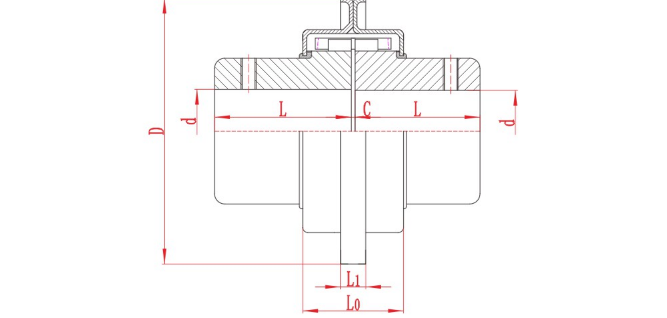
A crowned gear coupling transmits torque through meshing teeth. Compare the selected gear arrangement against the shaft spacing, bore and keyway, displacement and lubrication plan. Check which end or ends provide flexibility on the proposed drawing. Use the RONGXING DRIVE GICLZ drawing and model table to see which dimensions to compare. GICLZ crowned gear coupling.
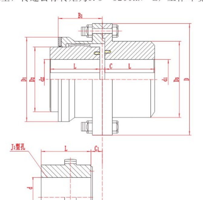
GICLZ catalogue section. Confirm the bore, hub engagement and shaft end spacing on the drawing for the selected model.
A grid coupling transmits torque through a spring grid between grooved hubs. Compare a grid design if you need torsional compliance. Ask how the selected model responds to the expected starts or reversals and confirm the lubrication and cover removal space. Where vibration is a design concern, review the torsional response of the assembled drive before changing stiffness. JSA grid coupling.
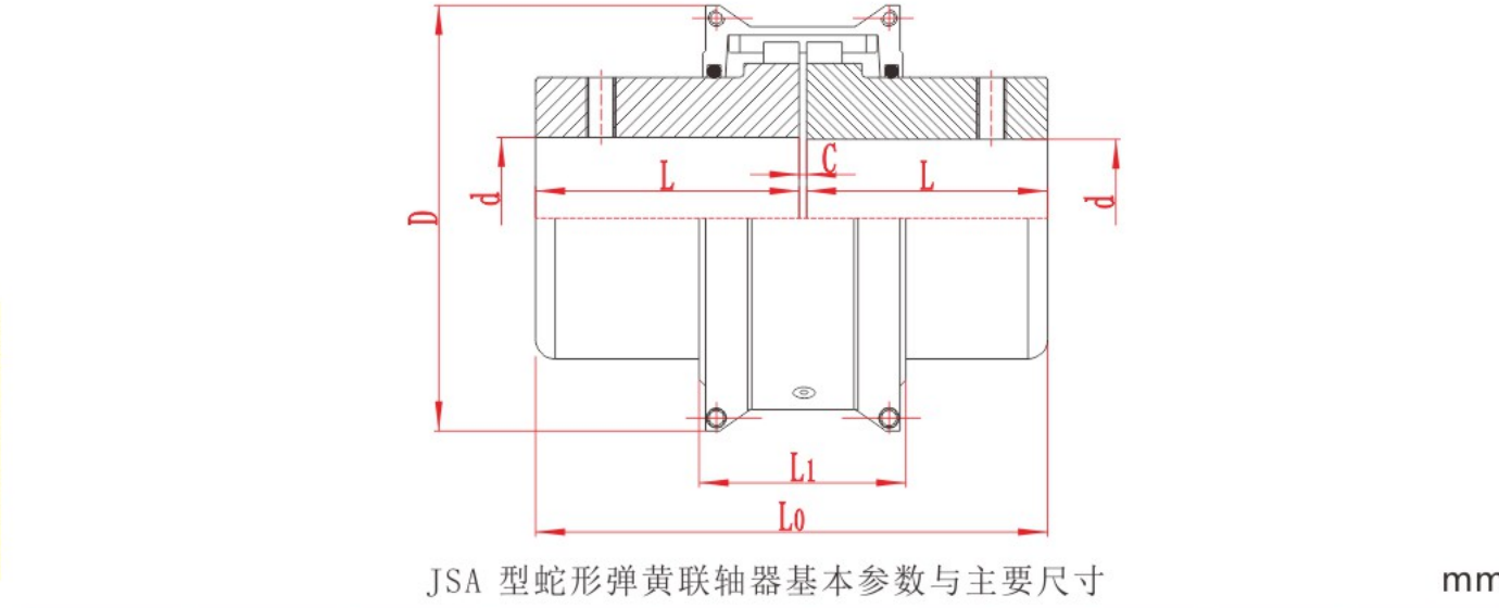
JSA catalogue section. Check the shaft end spacing and the space needed to remove the cover and service the grid.
Check cardan shaft geometry through the roll positions
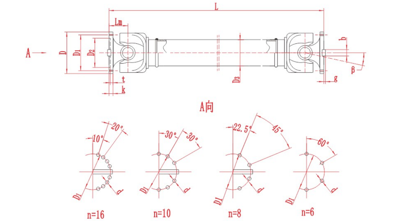
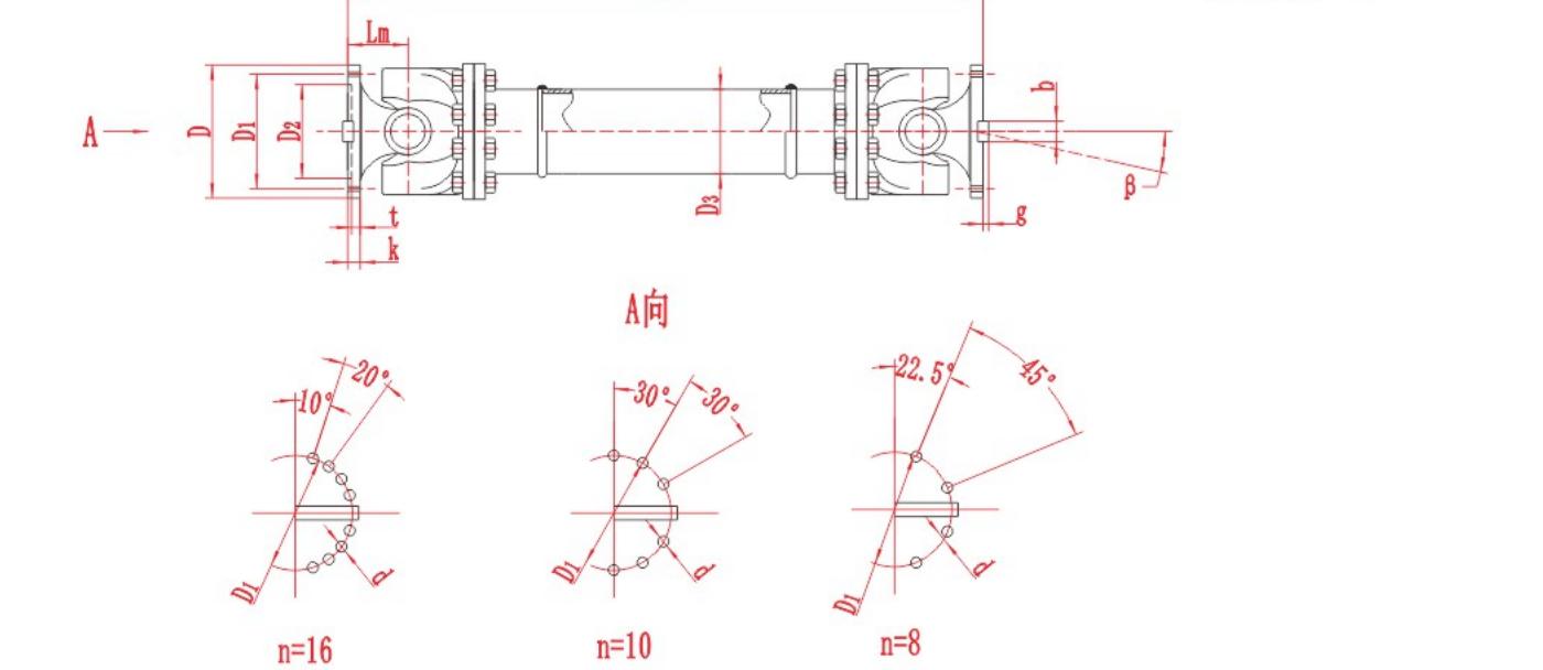
Show both machine axes at the normal position and at each relevant limit of travel. Confirm the joint arrangement and phasing, the angle at each joint, the required connected lengths and the actual speed and torque at those positions. For a telescopic shaft, check that the assembly has the required movement while retaining the specified engagement and clearances. The RONGXING DRIVE SWC-BH illustrates a telescopic welded configuration. SWC-BH product drawing and model data.
Check catalogue torque, speed and angle limits against the combinations that actually occur. Request the required dynamic review for the selected length and speed, including critical speed or torsional response where relevant. Rolling mill cardan shaft selection.
Check metallic flexible elements for the actual displacement
Disc and diaphragm couplings transmit torque through metallic flexible elements. Compare the actual element arrangement and the directions and amounts of movement it can accommodate. Ask for the proposed model’s stiffness and axial reaction data where these affect the drive or connected bearings. Check which limits apply simultaneously at the operating speed and temperature. For a preliminary diaphragm comparison, see the JZM configuration. JZM diaphragm coupling.
Prepare a comparison for the mill engineer
For a mill project in India, ask each supplier to review the same drive location and operating cases. Give the normal and highest speeds and the repeated and peak torque levels. Match them to the joint angles and shaft positions at which they occur. Add the bore or flange drawings, allowable envelope, operating temperature, contamination and the available maintenance access. Include lubrication, inspection and spares requirements when they affect the proposed structure.
Can I choose from the largest catalogue torque rating?
Use the torque rating for the exact model and its stated conditions. Check how the supplier treats continuous, repeated and exceptional loads. Compare the candidate with the speed, displacement, connection dimensions and lubrication requirements that apply to the same mill drive.
Should I use the same structure throughout the mill?
Choose at each connection. The input side of a gearbox, its output and a roll drive can have different speeds, torque histories and alignment requirements. A structure suitable for one position needs a separate review at the next.
For a preliminary RONGXING DRIVE comparison, provide the drive layout, operating cases and both connection drawings. Identify the specific position under review and ask for the proposed structure, model and its applicable limits. Send the mill drive data.