Technical Resources
How to Read a Gear Coupling Gap Chart and Check Alignment
To confirm a gear coupling installation gap, identify the series, size and assembly arrangement. Use the approved drawing or installation manual to find the specified distance, the two faces it is measured between and its tolerance. Record the actual
To confirm a gear coupling installation gap, identify the series, size and assembly arrangement. Use the approved drawing or installation manual to find the specified distance, the two faces it is measured between and its tolerance. Record the actual hub positions and any shaft end float or thermal movement that can change the distance in service. Confirm shaft alignment separately.
Which gap should you look up?
Match the series and size to the chart row, then check where the drawing puts the measurement faces. A shaft-end reading can differ from a hub-face reading when the hubs sit proud of or behind the shaft ends. A spacer arrangement can introduce another pair of reference faces.
| Dimension or reading | What to identify before using it |
|---|---|
| Hub-face gap | Identify the two hub faces called out on the drawing and the installed position of each hub on its shaft. |
| Distance between shaft ends | Identify the actual shaft ends. Check whether the drawing defines this distance directly and whether it applies to the selected assembly. |
| Spacer or intermediate member dimension | Check the spacer length and the drawing reference faces for the complete arrangement. Record which faces remain accessible with the spacer in place. |
| Gap variation around the faces | If the specified method uses face-gap readings for angular alignment, record the positions and measuring diameter. Use the specified alignment method to verify parallel offset. |
How to use the Rongxing GICL drawing with the chart
The Rongxing GICL assembly drawing shows C at the centre of the assembly. Read the arrow endpoints with the drawing and use the table for the exact model. The GICL catalogue also includes configuration details with C₁ and C₂. Confirm which detail applies to the ordered bore and hub arrangement before using a table value. Ask for the installation tolerance and setting condition if the assembly document does not state them.
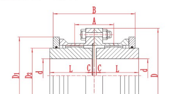
Use the GICL product drawing and model table to identify the assembly. If you still need to identify the size from bore or outside diameter, start with the GICL gear coupling size chart.
How does the installation gap relate to gear coupling alignment?
The axial gap sets the separation between the specified faces. Angular alignment checks the angle between the shaft centre lines, and parallel alignment checks their offset. A set of face-gap readings can show variation around the coupling when the approved method calls for it. Even readings can occur with parallel offset, so check offset with the specified dial indicator or laser method as well.
Use the installation limits specified for the coupling and driven equipment. A catalogue limit for coupling movement in service does not establish the acceptable alignment at installation. If the equipment has a cold alignment target or a defined running position, record the target and the position in which the readings were taken.
What information is needed to confirm a gear coupling installation gap?
Coupling identity: series, size, drawing number and revision, plus any spacer, hub orientation or special hub arrangement.
Dimensions and datums: mark the reference faces on a drawing or photo. Give the specified gap and tolerance in mm, measured gap in mm, shaft-end distance where relevant and the installed position of each hub.
Equipment condition: record whether readings were taken cold, and how each shaft was positioned within any axial end float. Include expected axial thermal movement or the equipment maker's cold setting when available.
Alignment report: include the method, any face-gap readings with their positions and measuring diameter, and the measured angular and parallel alignment against the applicable limits.
If the site reports a gap of 4 mm, first establish where it was measured. A 4 mm reading between the shaft ends cannot verify a 4 mm hub-face requirement unless the drawing and installed hub positions establish that the reference planes coincide. Use the approved specification to decide whether the measured gap is acceptable.