
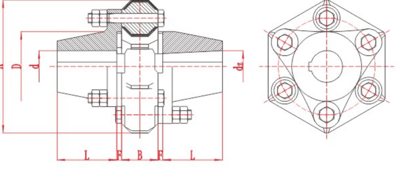
DL Multi-Jaw Coupling
DL Multi-Jaw Coupling with technical data and assembly drawing for preliminary selection.
View DL Multi-Jaw Coupling DetailsCurated technical topic
DL Multi-Jaw Coupling with technical data and assembly drawing for preliminary selection.
View DL Multi-Jaw Coupling Details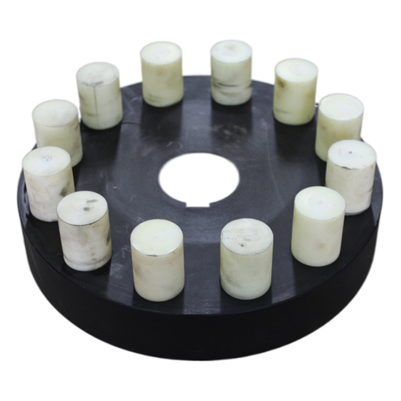
HL Flexible Pin Coupling with technical data and assembly drawing for preliminary selection.
View HL Flexible Pin Coupling Details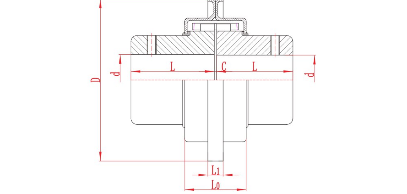
JSB Grid Coupling with technical data and assembly drawing for preliminary selection.
View JSB Grid Coupling Details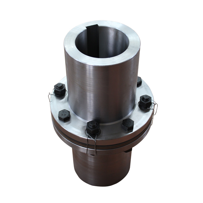
JZM Diaphragm Coupling for Heavy Machinery with technical data and assembly drawing for preliminary selection.
View JZM Diaphragm Coupling for Heavy Machinery Details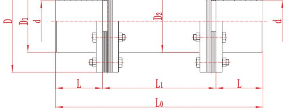
JZMJ Diaphragm Coupling for Heavy Machinery with technical data and assembly drawing for preliminary selection.
View JZMJ Diaphragm Coupling for Heavy Machinery Details
LA Tire Coupling with technical data and assembly drawing for preliminary selection.
View LA Tire Coupling Details
Choose a jaw coupling spider by matching the coupling series, size and insert profile first. Then confirm the specified material and hardness for the operating duty. The spider is the resilient insert between the two hubs. Shaft bore and coupling out

An elastomeric coupling connects two rotating shafts and transmits torque through a resilient element. Jaw couplings use a spider between the hubs, tyre couplings use a flexible ring, and some pin couplings use resilient bushes or sleeves. In industr
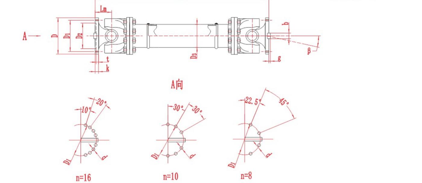
A universal joint coupling transmits rotation and torque between shafts that meet at an angle. In a cross-type joint, two fork-shaped yokes pivot on a four-armed cross. The joint can transmit torque while it articulates, but a single joint at a nonze
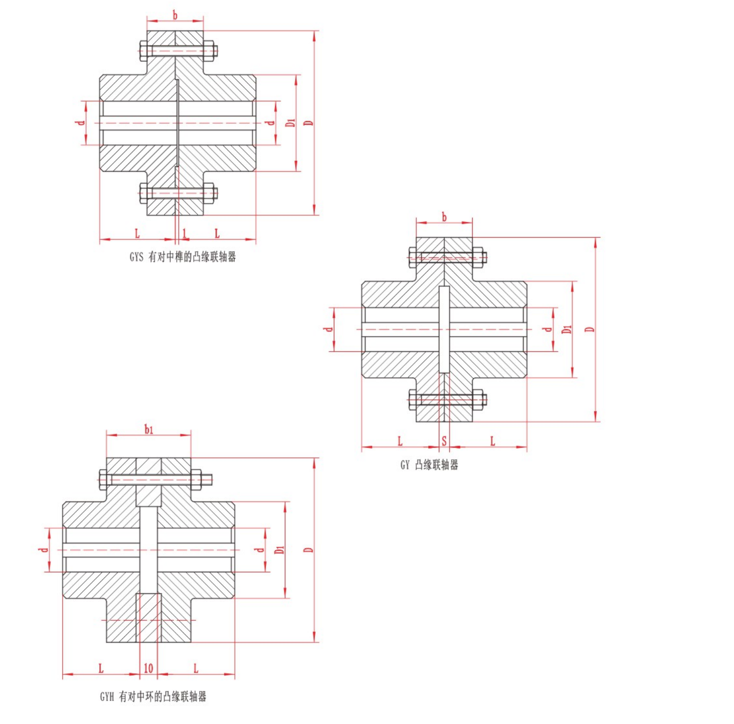
A shaft flange coupling transmits torque between two rotating shafts through flanges bolted together at their faces. In a rigid design, each flange is attached to its shaft and the bolted joint holds the two halves together. The machine must keep the

Start pin bush coupling selection with the load and speed at the coupling, then check both shaft ends and the space around the assembly. A pin bush coupling transmits torque through pins and resilient bushes between its flanges. The pins, bushes and
The two main types of mechanical shaft coupling are rigid and flexible. A rigid coupling joins shafts without a flexible element and depends on the required alignment being maintained. A flexible coupling accommodates limited movement within the limi
Send torque, speed, shaft and installation data for a preliminary review.